PUMP MAGAZINE: Questions and Answers
(91-100)
Question # 91: Dear
Sir
What is stelliting procedure on stainless steel, low alloy & carbon steel surfaces?
Regards,
Muhammad Abdullah
Fabrication Facilities Engineer
Answer:
Dear Muhammad:
I have asked my former colleague
Stellite hardface coatings
can be applied to metal parts by welding or flame spraying.
Welding typically uses plaza transfer arc (PTA) process, which creates a strong
metallurgical bond between the coating and the substrate material. Flame
spraying deposits Stellite powder on the substrate with a
high-velocity, high-temperature process, which results in a marginal
bond the quality of which is highly dependent on the part preparation
and process control. Both processes require post-coating machining/grinding
to achieve final part geometry.
For critical pump wear
parts, Stellite #12 and Stellite #6 applied with PTA on 316 type
stainless steel is generally suggested for rotating and stationary wear
faces, respectively. Specific application details should be discussed
with a process expert prior to finalizing procedure and material
selections.
*****************************************************************************************************************
Question # 92: I
would like to take advantage of this service by asking, what is the purpose of
a vortex plate attached to the bottom of the pipe in a suction type pumping
system that draws water from a storage tank?
Thank you for your
reply,
Al Saez
Answer: Al:
I think you
mean the plate submersed under the surface of the tank liquid level. First of
all, it is a good practice to make sure that the pipe carrying the liquid
entering the tank is submersed below the liquid level, at least 10-20 inches.
Otherwise, there is a considerable amount of air (if the tank open to
atmosphere) gets drawn in. Also, if the liquid level does not cover the opening
where the liquid exits the tank, toward the pump, the air is then likewise gets
drawn in, creating a surface vortex, or a submersed vortex. This vortex travels
a long way – and ends up at the pump suction, causing noise, loss of
performance, vibrations, seal damage, and other issues. The plate acts as a
baffle, helping break up the vortex. This holds true even if there is no liquid
flowing into the supply tank – the air vortex can get created even in case of
seemingly “non-turbulent” surface. Similar plates are used at the open sumps,
feeding the cooling tower pumps, vertical turbine pumps, and so on. They
disrupt the vortex, and eliminate, or minimize it. Of course, if proper
submergence exists in a tank, and the pipe is below the liquid level
(submersed), problems are reduced significantly. A tall tank is thus better
then a wide tank, for a given volume of liquid, because the liquid level is
higher, helping the suction issues as far as pumps are concerned.
I recommend
attending our
I hope this
helps,
Pump Magazine
*****************************************************************************************************************
Question #
93:
I am with the
Mike Janowski
San Antonio water Systems
Answer: Mike,
The types of pumps you mentioned are the types
normally used for sludges, and a PC pump is one of them. The $100 target is a
challenge, however, and most pump distributors would likely not want to bother,
and would send you to a Granger catalog, or similar. However, what about a
flexible vane impeller pump? - you can often find them at your local Home Depo,
or even a hardware store. Technically, they belong not to a centrifugal, but a
rotary class of pumps, but it should not matter. Essentially, it is a rubber
spider, eccentric to the casing within which it sits, attached to the shaft.
Vanes flex, filling the eccentricity void, as "impeller" rotates, and
the fluid gets moved from suction to discharge. Rubber is good for abrasives,
and the seal is typically a lip seal. At something like $20 per pump, you can probably
afford to replace the whole thing without any repairs, and, at any rate, at
such price, it could be worth the try.
Let me know how it works out!
Also, - you may consider attending our
Happy Pumping!
Pump Magazine
Follow-up question:
Thanks
for your help. We were thinking along
the same lines. I looked hard at the
flexible impeller pumps and they seemed ideal until I tried to size the pumps. While Shurflo makes the size that I need,
They are only rated for intermittent service (20min/hr. Jabsco makes one for continuous service but
delivers 3.5 gpm which is about 3 times the quantity that I desire. While I was ready to spring for the $200.00 per
pump, I was concerned about throttling or putting a rheostat on the line to
give me the one gallon that I need.
After searching the web all day, I am ready to take a chance on a
Gorman-Rupp oscillating lab pump.
"A vibrating coil works with a flexible bellows-type
impeller" This will pump 0.8 gpm
which is close to what I need. The price
with spade clips seems reasonable ($103.00).
I appreciate your help. I agree
that the flexible impeller seems to be the best choice. I just wish I could make the flows match what
I need. Ironically there may be a 12
volt DC pump out there that fills the bill, but when the same pump is hooked to
an AC motor the price jumps dramatically.
Mike
Follow-up comment:
Mike - I am
glad it was helpful. By the way, have you considered recirculating the extra
flow via by-pass line? It may seem like wasting energy, but, at the power
levels you have, it probably does not make any differences. Besides, with a
valve installed in recirculation line, and having extra flow capability, you
get yourself a system with variable flow ability - perhaps for the future.
Regarding the intermittent duty - I am not sure why they limit. At any rate, -
you seem to be narrowing down close to what you need - good luck!
*****************************************************************************************************************
Question #
94
Can you direct me to a source of information
that explains in depth the effects of VFD's on pump curves.
Thanks,
Jesse Vaverka
Answer: Jesse,
Changing speed results in changes in pump flow, head
and power, in accordance with so-called pump affinity laws for centrifugal
pumps: flow changes linearly, head as a square, and power as cube of speed
ratio. You may also take a look at several articles and Q&A dialogues at
the web site www.PumpingMachinery.com. If you have a specific pump curve at a
given speed, we can help you construct family of curves at other speeds that
you anticipate operation at.
Also, - I recommend you may consider attending our
Pumping Machinery
*****************************************************************************************************************
Question #
95: Dr. Nelik,
What is the best way to provide water
jacket cooling for dry-pit submersible sewage pumps when the owner
is against using the process sewage for cooling?
Thanks,
RK Engineers
Answer: Rob,
The user’s objection is probably a concern that the
jacket will get plugged up by the solids in the waste stream, which is not an
unusual situation, and their concern is real. Dry-pit submersible pumps are
also available with externally-supplied water for cooling jackets, which is in
compliance with their concerns. However, there are nowadays newer designs that
do not require neither pumped liquid, nor external liquid to cool the motor.
These designs have double set of seals, which contain specialty oil between
them. The first seal keeps the pumpage away from this “barrier” liquid, and the
second seal keeps the barrier from flooding into the motor windings. The oil
gets circulated by the pump-out ring (similar to how a double seal works with
Plan 52 external barrier container), and, by convection (not mixing of the two
streams), the heat is rejected from the oil to the pumped fluid. The only time
this (may) be an issue is if the pumped fluid is rather hot – although for
waste treatment applications this is not likely to be the case.
If you need a specific model recommendation, let me
know your specific requirements, and we will bring you in contact with the
right pump suppliers.
Also, - I recommend you may consider attending our
President
Pumping Machinery
*****************************************************************************************************************
Question #
96: Can someone help me? What I am looking for
is the formula to figure out questions like: If you have a duplex single acting
reciprocating pump making 170 strokes/minute, with a 5" diameter cylinder,
a 12" stroke and operating with 85% volumetric efficiency, what is the
capacity of this pump. as you can tell it is a coast guard question, and I have
been looking to find out how to solve these type of questions.
Thank you,
Note from the
Editors: Readers – please assist! – anyone in reciprocating pump world? –
please respond, we will forward your assistive answer to
Pump Magazine
Answer (by one of our readers): Hi
Lev,
Just couldn't
resist giving an answer for that one. I
stumbled on your web site and it's very good -
couldn't stop reading the Q&A section. I'm a machinery engineer in
the petroleum industry. We have steam pumps in the refinery that are nearly 100
years old and these types of questions come up. Everyone wants to know how much
the pump should deliver after it's been repaired - no one can tell if it's
repaired properly because our experienced mechanics are all retiring.
Flow = VE x pi
x (D/2)^2 x L x SPM x (# of throws)/231 =
= 0.85 x pi x
(5/2)^2 x 12 x 170 x 2 /231 = 295 USGPM
Brad Cassolato,
P.E.
Thanks, Brad!
****************************************************************************************************************
Question #
97: Dear Dr. Nelik,
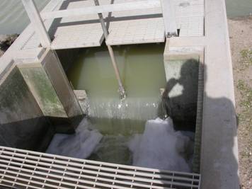
Our application is pumping of treated
wastewater effluent from a secondary treatment pond into a tertiary DynaSand
filter system. Since the wastewater flow is higher during the
day we would like to use the pond for flow equalization by allowing the level
to rise by about 4 inches during the day and return to normal level after
pumping all night. This would allow the DynaSand filters to operate at a
constant flow rate over a 24 hour period which minimizes the need for over
sizing of the filters to handle peak flows. The ponds currently discharge
through an effluent structure that sets the overflow height for the pond.
This effluent structure would have to be constantly adjusted to obtain the flow
equalization capability. I would like to leave the effluent structure as
a backup anyway so it would simplify the treatment process if I can pump
directly out of the ponds (there are three of them).
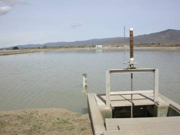
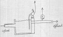
I would like to install a self-priming pump
adjacent to each of the three ponds and pump directly out of the ponds.
The water depth is only about 5 feet deep in this area and I was wondering what
special arrangements would be necessary to avoid problems such as scouring of
the pond bottom, air entrainment, etc.
I need to pump 2,000 gpd from an
existing large secondary lagoon at a wastewater treatment plant.
Rather than construct a pump station off of the existing effluent line, I would
like to use a self-priming pump located on a concrete pad on the bank.
This will allow use of the lagoon for flow equalization. In this mode,
the lagoon will have a minimum water depth of 5 feet. Are there any special
considerations you would recommend for the intake line from the lagoon to
the pump? Also, do you have a recommendation for the pump itself?
Allied Engineers, Inc
Pump Magazine has asked
Secondary treatment in a Lagoon is usually accomplished with algae, which could cause some problems on a pump strainer. However since you are pumping to a filter maybe you don't need a strainer on the pump suction. It is possible to add some chemicals to the influent to the pond, like ferric chloride to remove phosphorus, which could conceivably cause corrosion problems on the pumps (ferric chloride is an excellent corrosion agent often used in corrosion tests). While I like the idea of equalizing the flow to the filter, I'm not sure that you should let the filter dry up for long periods of time. The solids deposited on the filter bed actually act as filter media and catch finer material then the sand could alone as the filter operates. Drying the bed intermittently will probably let more material go through the filter. It would be a better idea to try to maintain a constant flow to the filter rather then on and off operation.
Alternatively, there are some reasons to only discharge during the day; Note that dissolved oxygen fluctuates as the pond alternately is subjected to sunshine and then darkness. Algae creates oxygen and consumes carbon dioxide with sunshine and consumes oxygen and creates carbon dioxide when sunlight isn't available. This cycle creates a fluctuation in the Pond PH as carbon dioxide is created and destroyed. Discharging only during the day could allow more oxygen to be present in the effluent and a slightly higher PH as well. Luckily most permits allow a PH range of 6 to 9.
Ideally a final
equalization pond after the filters with some mixing might allow for better
system effluents.
City of
Water and Waste
Treatment, Engineering Applications
*****************************************************************************************************************
Question # 98:
Dear Dr. Pump:
I thought I knew about sewage lift station until I ran
into this unique situation. I think I
found the answer, but I like to have a second opinion. We like to convey
settled sewage (septic tank effluent 20 to 30 gpm) from high elevation of 2000 ft to low
elevation 1650 ft. Gravity sewer is cost
prohibitive along a narrow winding road with number of culverts and a number of
humps and dips along the way. I am thinking about using 1.5 inch or 2 inch
diameter , 1.7 mile long force main and
a Positive Displacement pump.
Questions:
Is downhill pumping feasible with a PD pump?
What are the design issues?(such as slip due to low
viscosity, column separation due to downward slope of force main, air
release/vacuum release at high points?
Which of the 4 types of PD pumps will be better for
this application? Any recommendation of
manufacturers?
If we do not use any air/vacuum release valves, can
the PD pump push the air without loosing efficiency or pressure surges? Pressure surge probably won’t be an issue as
it will occur only after air goes out of the outlet 1.9 miles from the pump.
Any design suggestions from you or your readers will
be appreciated. If you have a case study
or a similar project, it would be even better.
I am thinking that using centrifugal pump is not a
good idea at all. Do you agree?
I am still debating about a semi-positive displacement
type grinder pump (such as Environmental One).
E-One is essentially a centrifugal pump with almost vertical pump curve,
and I am not sure if it can handle negative head? Manufacturer said it can.
Satgur
Atlanta, GA
Answer (preliminary): Satgur, - we are posting your
questions at our Q&A web section, and asking readers from the water and
wastewater industry to comment, and will let you know what they recommend.
From my view – you are absolutely correct, -
pumping downhill is more involved then uphill. Local water column separations
can occur, and intermittent air pockets may even produce vacuum zones,
potentially collapsing the pipe walls. A positive displacement pump, such as
progressing cavity, may help control the flow, but gravity may accelerate the
downstream flow of the fluid faster then the pump delivers. It would be
difficult to select the pump to pump faster then gravity, as free acceleration
can speed up the flow stream very significantly.
Let’s see what others comment.
Dr. Lev Nelik, P.E.
Pump Magazine
We have recently received additional
feedback from
I'm not sure I could recommend any pump for this
application. In my experience in the
coal industry I have seen antifreeze solutions and other chemicals siphoned
through gear pumps and I believe it would also happen in progressive cavity
pumps at much lower heads. The only pump
that I think might be capable of doing this job would be a ball and check
valve, then the vacuum would probably still create slam problems on the valves
or balls etc... You are correct that a
centrifugal pump is a bad idea in the application since gear pump can be siphoned
through. A centrifugal would (likely)
allow much easier siphoning through them.
I know you are
trying to kill head with the small line, but you may create plugging problems
for yourself if you use too small of a line.
There is then the possibility of bulk transfer, with higher head loss,
but this again causes problems at the end of the transfer--air has to enter the
line and/or air will come out of solution easily under very low vacuum. Water hammer could become a real problem if
air enters the line in gulps and then is allowed to expand and contract with
the pressure increases and decreases.
I believe that
perhaps your best chance of lower this fluid 350' would be to have about 3
intermediate tanks, at which the vacuum is relieved. When the fluid enters these tanks it could go
in tangentially and then run into some kind of a dissipation barrier. If you don't relieve the vacuum you can
implode a line--I have seen pictures of a large water main in
Perhaps another
somewhat unusual idea would be to actually generate electricity with the
lowering device. The City of
City of
*****************************************************************************************************************
Question # 99: Is there any guideline or standard in API
calling the necessary bolt tension when fastening the pump skid onto a steel
foundation base? In our normal practice, we just hammer the wrench till it is
presumably tightened. Torque wrench is never used except rare cases such as
diesel engines.
Please advice.
Thanks and regards
Choong KW
Keppel FELS, Mechanical department
Answer:
API 610 now has guidance for bolting in NOTE 2 following clause 5.3.4. It
reads as follows: "For bolting, the allowable tensile stress is used
to determine the total bolt loading area based on hydrostatic load or gasket
preload. It is recognized that to provide the initial load required to
obtain a reliable bolted joint, the bolting will be tightened to produce a
tensile stress higher than the design tensile stress. Values in the range
of 0.7 times yield are common."
In general, for all bolting subject to dynamic
loading, it is important to apply a preload torque that gives a tensile stress
higher than the tensile stress the bolts will be subjected to in service
to avoid stress cycling. Usually a preload stress equal to approximately 70% of
the bolt material ultimate tensile strength will accomplish this.
Pump Magazine
*****************************************************************************************************************
Question #
100:
I've been characterizing the properties of Pulp and
Paper "Black Liquor". In Pulp and Paper processing, Black liquor
(principally lignin and digester chemicals) is concentrated to approximately
70-80% total solids and burned for chemical reuse and energy. I have just
recently acquired a viscometer which is yielding lots of data. This data
suggests that the liquid processes thixotropic non-Newtonian behavior. Meaning
that the viscosity is dependent (and lower) at high shear rates, and it also
has some memory (the viscosity is lower at a certain shear rate after it was
subjected to higher shear rates some time period prior).
The evaporation process uses many very large
circulation pumps. I'm wondering to what
effect the liquor is shear-thinned when in the large circulation pumps. Of
particular interest is to determine or quantify the maximum shear rate in
a centrifugal pump.
Intuitively, it seems logical to say that the shear rate is much larger
in the pump than in the downstream piping, but quantatively how much? Is there a relationship that relates shear
rate to RPM, impeller diameter, Max impeller diameter, TDH, and rate? If that
information is not available what order of magnitude is typically obtained?
Below is one example of a pump that is typically used
for the very difficult service
Model:
3180/3185- Goulds
Size: 10X12-16
(Diameter=14.606 x 12.953")
5 VANE OPEN
RPM=1180
50' TDH, 4950 GPM
In addition to that, I use a variable speed pump for
piloting. Any info that can be used to
estimate the shear rate for this pump would also be helpful.
Min=1600 rpm
Max=2800
Model: 3x2-10
Semi open impeller
Flow=45-70 gpm
Thank you very much.
Joe Rydberg
Answer:
Joe, - a very interesting question. The nature of flow within the pump
internals, particularly within the blade cascade, is complex, and the subject
can easily take off on a very theoretical road, plus some laboratory
experimentations, and probably a good Ph.D. topic for the university. The power
transmitted to the pump by the motor is transmitted to the pumped fluid, which
is resisted to motion by the internal friction. This friction is a between the
fluid particles and the boundaries near which particles flow, such as casing
alls, impeller blades, etc. The internal friction within the fluid itself
generates some heat, but it does not contribute to the friction resisting the
movement. Power is torque times speed, and torque is force times moment arm,
and force is shear stress times area. And shear rate is viscosity times shear
rate. The shear rate depends on the velocity profile. In a circular pipe with
laminar flow, for example, this profile is a parabola, and for turbulent flow
this parabola looks more like an arch of a bow, - with high deflection rate at
the ends, and smoother near the center. What matters is the rate near the wall,
i.e. within the very thin layer, called a boundary layer.
By taking this rate dU/dN (change of velocity by the
normal distance perpendicular to the wall, within the boundary layer, is a
shear rate. If we then multiply it by viscosity, we get shear stress, and then
the rest is easy. As you observed, viscosity is constant for the Newtonian
fluids (such as water), but for some it is not, and changes with the shear rate
itself. Measuring its change is difficult, and can best obtain in a research
environment. In practice, however, pump manufacturers, as well as some mills,
have developed empirical factors, to help size the motors properly, to
accommodate the non-Newtonian behavior of various fluids, including black
liquor at paper mills. There is a Paper Institute in
Hydraulic Institute has developed charts to show flow,
head and efficiency corrections for centrifugal pumps at various viscosities,
as compared to water. Pump Magazine asked
Lev,
A few years ago, we did some performance testing of an open
impeller pump that was pumping black liquor at various
concentrations at a customer's site. The conclusion at the time was
that using the HI correction factors for pump performance gave fairly accurate
performance predictions of the pump. Therefore, my recommendation would
be to estimate the viscosity and use the HI correction factor. I do not
believe the effect of shear rate is large enough to cause concern in this
application. If more information is required, the customer can be referred
to the Goulds applications department.
ITT Goulds Pumps
Pump Magazine has also heard from
Lev,
Mr. Mike Day is
the expert on black liquor pump application. All of the engineering had been
worked out in the 60's and 70's. By the time I got there this was firmly entrenched
in the realm of Applications and I believe that they had a fairly rote system
for choosing pumps based on liquor concentration among other things. I have a
What would be
interesting to investigate perhaps is the role that control valve in the
previous stage plays in the shear thinning characteristics of the liquor or the
effect that something such as slotting the sideplate would have (if any). I
never got to study these things.
One cautionary
note - your correspondent seems to be pointed in the direction of increasing
the shear rate in order to reduce the 'working viscosity' and thereby reduce
the overall power consumption. He must be careful not to increase the NPSHr as
I believe this application is a cavitation risk owing to the temperature and
possible fluctuating suction pressures between stages. Also, black liquor pumps
are subject to erosive wear because they can have a high 'tramp sand' content
entrained in the liquor. Pumps with higher shear rates would tend to accelerate
this problem.
Hope this helps.
Best regards,
A follow-up comments from the user:
Thank you for the
quick response. It is well understood, for laminar flow, the shear rate of a
Newtonian fluid in a pipe is given as = 8V/D, where V=velocity, D= Pipe
Diameter. For my applications this
corresponds to ~110 or so... And
correlations are also available for non-Newtonian fluids in pipes in laminar
and turbulent regimes.
I appreciate the cautionary comments concerning the
questionable thixotropic behaviors of the black liquor. I will keep those in mind as I continue my
work.
Some of the differences in viscosity that I'm
measuring are fairly substantial and can differ largely as a function of
feedstock. This knowledge of viscosity
is helpful in other design criteria, such as pressure drops through downstream
piping and heaters etc.
With that being said, I still wonder if the shear rate
within the pump is the same order of magnitude at 100s-1 or
is it much larger?
Any additional info would be greatly appreciated.
Joe Rydberg
From the Pump Magazine:
Joe, - there
are two kinds of shear action inside the pump, particularly the vane cascade.
The first is essentially similar to the pipe analogy that you described,
because the passage between the vanes is essentially a large channel, although
with walls being an odd shape as compared to perfect pipe. Flow is usually
turbulent, since centrifugal pumps typically handle low viscosity, and thus
Reynolds number is fairly high. The second type of shear is within the
clearances between the vanes and the casing, as well as between the flanks of
vanes (for the open impellers, which are typically used for pulp and paper) and
the wear plates. This clearance is on the order of roughly 0.030”. If you take
a 1200 rpm pump, the tip speed at its 16” impeller is 84 ft/sec, and thus,
assuming the clearance is entirely occupied by the boundary layer, would be
(84x12)/0.030 = 33,500 sec-1, i.e. substantially greater then your
100s-1. Keep in mind, however, that the impact of this “second kind”
of the shear is small, as it affects only a very small proportion of flow,
while the bulk of the flow experiences a much lower shear. In some case,
however, it matters. For example, pumps pumping clear transparent fluids (some
perfumes for example) can affect the quality of the entire batch by contaminating
it with the small impurity of “cloudiness” coming off even small region of the
between-the-clearances flow. For most case, and I suspect yours in probably in
that later category, the overall impact is negligible and practically
unimportant.
I think
your viscosity of black liquor in motion at the entrance to the pump is greater
then at rest – due to the thixotropic behavior, - and that part you seem to
have already covered via your testing. You can probably assume the additional
thinning of fluid as it goes through the pump is negligible, per discussion
above. Thus, you will have only two values to worry about: high viscosity at
rest, requiring bigger motor to get the pump going, and then a moving
viscosity, that being roughly the same at both inlet and exit, of the pump.
Thus, from the operating costs, that would determine the energy required.
I hope
this additional discussion is helpful. Good luck in your work, keep us posted.
If we hear any further feedback from our readers, we will certainly let you
know.
Regards,
Dr. Lev
Nelik, P.E., APICS
Pump
Magazine
Note: Pump Magazine would like to hear input and comments from
our readers. Behavior of non-Newtonian fluids is unique is not widely explored;
your thoughts and ideas will be appreciated.
CLICK
HERE TO SUBMIT YOUR QUESTION