PUMP MAGAZINE: Questions and Answers
(31-50)
Editorial staff
continuously updates Q&A section by adding new questions and answers, based
on our readers’ interest, input and feedback.
*******************************************************************************
Question 31: Dear Dr Pump,
We have a Progressive Cavity pump and working to
discharge Bitumen. This pump is sucking the bitumen from a tanker through a
flexible hose. The problem is that after all bitumen is sucked from this
tanker, some of it remains unsuckable in the suction hose. This regularly
happens and it is a daily headache for the end user. My question is as follow:
why this pump can not make stripping after each delivery? Please reply by
return and advise how can we solve this problem.
THANKS & B.R
AHMED SOBHI
SALES MANAGER
ROTATING EQUIPMENT DIVISION
DAFF TRADING & OIL SERVICES EST.
POB 7399
Answer: Dear
Ahmed,
This is what I think is happening:
Pump people have an expression: “If you get the stuff to the pump,
- we can pump it!” – and there is some truth in it. Before a pump can move the
fluid out, the fluid must first get to it. The pump does not actually suck the
fluid, - what it does is moving the fluid out into discharge, creating space
for more fluid to get in. What makes the fluid to get in is suction pressure.
On the surface of your tank you probably have atmospheric pressure. The height
of the fluid adds to that pressure. As tank empties, the level drops, and thus
total suction pressure drops. There are friction losses in the suction pipe (or
hose) and suction pressure must overcome that. If suction pressure is not
enough to overcome theses losses – no pumping. The more viscous the fluid, the
more this would be an issue. Bitumen is typically very viscous.
Also,
as the level drops and gets to the point that the inlet port is exposed to the
air, it may be getting into the pipe, creating additional problem.
Couple
of things you may consider:
a)
Make sure the pump is as close to the tank as possible, i.e. make
the connecting line as short as you practically can
b)
Make sure the hose is not blocked, kinked or cut, allowing air to
get in somewhere along its length
c)
See if the pipe connected to the tank is at as low level as
possible – maybe take it from the very bottom?
d)
Perhaps use a larger hose, to reduce friction?
e)
Would it be possible to preheat the bitumen to make it less
viscous to flow better? (at least at the end)
I am also forwarding your
question to Mr. Tate Coghlan, who is a US Regional Manager for Monoflo Pumps, a manufacturer of Progressing Cavity pumps. They
may have additional suggestion, and could also help you locally via their
international office, if the problem still exists.
Let us
know if these suggestions helped.
Best
regards,
Dr. Lev
Nelik, P.E., Apics
Pump
Magazine & Pumping Machinery
*******************************************************************************
Question 32: Dear Dr. Pump, Happy New
Year!
Can you tell me more about the effect of temperature on NPSHR?
I know that result of test of NPSHR with warm water is less than with cold
water, but I would like to know, why? What are the technical reasons for this?
Best regards,
M. Moloudy
Answer: The cold water
is a much “tougher” with regard to cavitation as compared to warm water. The
explanation goes back to the fundamentals of thermodynamics of cavitation. The
vaporization (boiling) of liquid in the process of cavitation is a thermal
process, and depends on fluid properties, such as pressure, temperature, latent
heat of vaporization and specific heat. To make vapor form, the latent heat of
vaporization must be derived from the liquid flowing through the pump. This
flow of heat can only be possible when the liquid temperature is above the
saturation temperature at the main pressure in the low-pressure zone where
cavitation is about to begin. In other words, the pressure in the cavitation
region must fall below the saturation pressure corresponding to the liquid
temperature.
As we know, pump head begins to drop when cavitation begins – as
bubbles block the passages more and more. Keep in mind that the term “pump
head” ultimately means “energy per unit of mass flowing through the pump”. This
energy (i.e. enthalpy) is related to specific heat as:
Dhf = CL x DT
This heat transfers transforms some liquid into vapor. The ratio
of the resulting vapor volume to the remaining liquid volume would determine
the extent of blockage of the passage by vapor. “B” is a thermal
criterion, defined as:
B = (Vvapor
/ Vliquid) x (Dhf
/ L)=(Vvapor / Vliquid) x CL x DT
As you
can see, the “blockage of the impeller passage” is directly proportional to the
latent heat, i.e. more pronounced for cold water then warm water.
This affects
not only loss in performance, but also the damage to the pump. Vaporization
causes performance drop, but their eventual collapse (implosions), as they move
on to a higher-pressure zone, is likewise more violent for cold water, as
compared to warm – for the same reason, back to enthalpy and specific and
latent heat.
In
fact, the analogy can also be extended to hydrocarbons. As you know, API allows
NPSH corrections for hydrocarbons, versus tests on cold water. The reason –
hydrocarbons are less damaging from the cavitation standpoint, as compared to
water. In practice, however, this rule is not usually enforced, as most people
prefer to rather have some safe margin of NPSH, instead of cutting “too close
to the wire”.
I hope
this helps with your question. There is more to it, but is too technical to
cover here, although we would be glad to provide you with a more detailed
explanation if you should need. Please note that many of the NPSH-related
aspects are covered during the Pump School classes, and you are welcome to
check the schedule and the Agenda at the PUMP SCHOOL (click) section of the Pump
Magazine.
Regards,
Dr. Lev
Nelik, P.E., Apics
Pump
Magazine
*******************************************************************************
Question 33: Hi,
I would like to learn how the NPSH test of a pump is
performed. Would you please explain the method by an example?
Thanks,
A. Kiziltan
Answer: Dear Mr. Kiziltan,
 Pump
manufacturers conduct NPSHR tests in one of two ways: either by throttling the
suction valve, or by vacuum tank.
Pump
manufacturers conduct NPSHR tests in one of two ways: either by throttling the
suction valve, or by vacuum tank.
![]() a) Valve
throttling at several flows:
a) Valve
throttling at several flows:
![]()
![]()

![]()
![]()
![]()
At each flow, as valve is throttled, the suction pressure at the
pump suction flange drops, i.e. available NPSH (NPSHA) gets lower and lower. At
some point, cavitation begins, and with it, pump Head begins to drop. When it
drops by 3%, the value of NPSHA there is what is called NPSH-required, i.e.
NPSHR.
At example above, values for NPSHR are obtained at (4) flows.
Then, these (4) values of NPSHR (the 3% note NPSHR3% is usually
omitted) are cross-plotted versus flow, which is what you see pump
manufacturers publish in their catalogs, called a pump NPSH-curve:
NPSHR

b) Another method is reducing suction pressure by
providing vacuum (called Vacuum Suppression Test) on the surface of the closed suction
tank. The rest of the procedure is the same as in (a).
Each methods has its benefits and drawbacks. Vacuum testing (b) is
more “pure”, since there is no disturbance in the inlet pipe by the throttled
valve, so for a more “scientific” experiment this may be preferred. The valve
method is simpler, and cruder so to speak. Depending on the type of a valve,
its position, etc., the results could be a little different. However, in
practice, pumps always have some sort of disturbance-causing equipment in line,
and thus represents a more real (“field”) situation. It will likely produce a
more conservative results, which is better from the standpoint of some extra
margin of NPSH.
For more information – please apply a SEARCH function on the
Home Page of Pump Magazine. There are several articles and questions posted,
which you may find helpful, regarding the NPSH topic.
Let us know if this helps,
Regards,
Dr. Lev Nelik, P.E.
Editor, Pump Magazine
*******************************************************************************
Question 34: Dear Dr. Pump
One of the consultants put a condition for sewage pump
suction, which is the velocity of the liquid at the eye of the impeller should
not exceed 3.7 m/sec, and that is for the submersible sewage pumps. Please advise
us the technical reasons for such condition?
In addition to that, we want to know how can this
parameter (eye velocity) be reduced, and what other factors could effect that?
Thanks and best regards,
AHMED SOBHI
SALES MANAGER
ROTATING EQUIPMENT DIVISION
DAFF TRADING&OIL SERVICES EST.
Answer: Your consultant
is right being concerned with velocity at the suction pipe. The higher the
velocity – the more are the hydraulic losses and less is static pressure that
remains at the pump inlet, which reduces NPSHAvailable. An approximate
rule-of-thumb number for suction velocity is 5-10 ft/sec (1.5 – 3 m/sec), which
is used to size the suction pipe.
Among other important parameters is the distance from the pump
inlet to the bottom of the sump, as well as distances from the pump and side
walls of the sump. Pump submergence is important also, to make sure there is no
entrapped air or vertexes that can get “sucked-in” and cause loss of
performance, vibration, and damage. To recommend exact numbers, we would need
to know more details, such as pump size, performance, geometry, NPSHA, sump
diagram, etc.
Another important factor for water, sewage and, especially,
marine, applications, is a choice of materials. These applications often have
problems by the combined attack of corrosive environment (for example salt
water or brine), as well as abrasion (entrapped sand, run-off debris, etc.),
plus cavitation. Bronze impellers are known to have problems, but even
stainless steel could be prone to short life. You may consider engineered
composites materials, such as Simsite, which is graphite fiber based composite
(it is not plastic), with strength similar to metal, and 3-5 longer life as
compared to bronze. Prime examples are marine applications, Navy, ship pumps,
and sewage treatment usage.
You can use SEARCH function on the front page of Pump Magazine to
read more about NPSH, cavitation, Simsite, and related topics.
I hope this helps,
Best regards,
Pump Magazine
*******************************************************************************
Question 35: Good afternoon Dr Pump,
I have read many of your papers and found them all very
informative and most useful. I wonder if you can help me out with some
ammunition. I have a chilled water circulation pump that destroys itself within
weeks of start-up. I have told the OEM that I want a pump with a more robust
construction and have found the L3/D4 number is 85 (US units) (in metric units
equivalent to 5). I have read somewhere that the industry standard is 60
(1/inches, English) but I can’t find any standard to back up my argument.
Can you help?
Regards,
Keith Townson
Senior Rotating Equipment Engineer
Qatar Petroleum
Answer:
Dear Keith,
Take a look at Article #4 of Pump Magazine, where there is more
discussion on L3/D4 criteria. The so-called
“L-cubed-over-D-to-the-fourth” is a criterion of a rotor stiffness, i.e. its
ability to resist deflection by the load. You are correct, single-stage
overhung impeller type pumps have this ratio vary between 20-120 – obviously,
the lower the better.
There is no standard actually, where the number is specified, but
the users, engineering firms, or contractors, sometimes specify the number,
when they want to ensure equipment is robust and reliability is particularly
important.
Do not overlook another very important factor. Shaft deflection
(y) is directly proportional to the load, overhung length
(“cubed”), and inversely to the shaft moment of inertia (where D
is in 4th power). That is how the “L3/D4” factor comes in. When we
compare the L3/D4 numbers, it is usually assumed that we are talking about the
same load. The weight (W) of the impeller adds to the load. If this weight is
reduced, the load is less, deflections are less, and life is longer. For many
applications (and, by the way, a previous reader’s question relates to this
too), - if the metallic impeller is replaced by a non-metallic impeller, the
effect on reliability improvement can be dramatic.
y = k x (W) x (L3/D4) –
i.e. “W” has as much effect as L3/D4 !
The problem is that plastic pumps impellers, while very good from
the corrosion standpoint, are not strong enough, and have limited temperature
capability. Structural composites, however, do not have these limitations. For
example, Simsite structural composites, manufactured by Sims Pump company, have
strength equal to metal, excellent resistance to corrosion, and superior
cavitation characteristics. It outlasts bronze by a factor of five,
which is why it is an excellent material for marine and navy applications, such
as seawater pumps, desalinization stations, water and waste treatment, where
their abrasive characteristic against sand and particulates makes them a choice
material. Simsite weighs only 20% of metal, which means dramatic
reduction in deflections and very significant equipment life improvement.
When a particular application has a problem, it is not easy to
change the L3D4 shaft ratio, but replacing the impeller is simple, and has an
immediate effect of 3-5 times life improvement. Of course, for new
installations, it makes sense to even get a complete pump made from the Simsite
material, especially if corrosion and abrasion are considerations.
I imagine in the Middle East, where your company is based, this
material could provide an excellent solution to numerous reliability problems
in the ocean water applications, salt water pumps, marine and navy pumps, as
well as water purification and desalinization projects. Utility plants, using
salt water for cooling pumps, as well as brine applications, are another
example.
You can do a SEARCH function on Sims material at
the front page of the Pump Magazine section.
Let us know if this information was helpful,
Pump Magazine
*******************************************************************************
Question 36: Dear Dr. –
I'm a new reader and I appreciate your magazine very much.
I've just read the Article #10 about Pump-Out Vanes and I'm one of that guys
that would like to spend nights without sleep reading something about new
things in pumps. As you wrote in the article I'd like to have more material
about that, so if you can get to me the material I'll appreciate it very much.
I have already a book by Stepanoff which is, I think, is
one of the most important ones, and Lobanoff too, but I didn't know about
Zanker and others. I appreciated really much your way of explaining complex
things in a simple language, to answer and clarify questions, without
sacrificing the technical part.
So please let me know.
Best regards
M. Meana
Answer: Thank you for
your kind compliments. Stepanoff’s book is truly an excellent source of information
for the pump designers. It covers a variety of pump topics, including axial
thrust. However, it does not cover fully how thrust varies with the variation
in the gap between the pump-out vanes and the stationary wall of the casing.
Nor does it cover the effect of the pump-out vane height. These could be very
significant. A plus (+)1000 pounds of axial thrust toward the
impeller eye could become a +1400 pounds, or even minus (-)600
pounds thrust in the opposite direction if the gap changes, or the vanes get
machined off, or worn out. In case of open impellers with adjustable front
clearance (impeller to casing), the reason and justification for the
adjustability feature is the ability to restore the gap, thus reducing the
front leakage and restore the efficiency back to the original “non-worn” value.
But, - the movement of the impeller forward also opens up the gap in the back!
While the back side of the impeller has little effect on efficiency, it does so
on axial thrust! New problems with bearings overload, seal leakage, etc. may,
or sometime do, pop up – all of a sudden, as far as a pump user sees it.
For general information on pumps types, equipment reliability
questions – from the pump users point of view, we recommend a book (click on) “Centrifugal
and Rotary Pumps: Fundamentals with Applications”, by CRC Press,
1999. Zanker’s paper, to which you are also referring, is essentially a
detailed research publication (about 15-20 pages), and deals with the pump-out
vanes and their effects in much greater detail. At this time, PUMP MAGAZINE is
working on putting together a CD with a complete set of Pump Course Notes (200
pages), which will be available for sale for $200 (shipping is free within the US;
add $10 for international). We could send you an advanced copy of the CD and
include Zanker’s paper on it if you would like.
*******************************************************************************
Question 37: Dear Dr. Pump,
I want to know the difference between pumps with API-610
and ISO standards.
Would you please explain the differences between pumps
manufactured based on API-610 and pumps per ISO standard per following points:
1. LIFE TIME OF
THE PUMPS
2. LIFE TIME OF
BEARINGS
3. VIBRATION
LIMITS
4. ALLOWABLE
NOZZLE LOADS
5. BALANCING
6. BEST
EFFICIENCY POINT LIMITATIONS
7. ALLOWABLE
DESIGN PRESSURE
8. MIN. MATERIAL
ALLOWANCE
9. SEALING
STANDARDS
10. BEARING OIL
LUBRICATION
11. MIN.
CORRESION ALLOWANCE
Best Regards,
H.R. Pourahmadian
Machinery Dept.
Answer:
Dear Mr. Pourahmadian,
There are several main standards covering pumps. They came about
at different times and by and/or for different markets and industries. Among
the most known are Hydraulic Institute, ANSI, ISO, API and PIP.
Hydraulic Institute. This is
mostly generic, and not as detailed. It deals with definitions, pumps
classification, types and nomenclature. Back in 1950s, when the US pump world
basically consisted of 5-6 major pump conglomerates (Ingersoll-Rand,
Worthington, Allis-Chalmers, Byron-Jackson, United, and a few others), the
Hydraulic Institute basically represented a “club” where top executives would
periodically meet, talk about business, relax and see what is going on. At that
time, it was (and still is) a very prestigious organization, with membership
fees to $15,000 or even more. Naturally, smaller companies did not belong.
As time went on, a pressure to produce more “tangibles”, and less
good-time-chat, started to shift the nature of the HI into having more
technical committees, with executives making room for engineers, who would
produce recommendations on things like sump design dimensions, pump
efficiencies, vibration levels, etc. The fees dropped, so that smaller
companies began to be able to rub shoulders with the “big guys”, at a “meager”
$3000 or so.
As a result, the HI is undergoing a transformation towards a more
practical, results-oriented organization. It will take some time, and the
present HI publications are still mainly useful for larger pump manufacturers
who deal with sophisticated pump users, and large engineering houses. HI is
putting a lot of effort into meetings and conferences to discuss and address
pumps reliability, equipment life extension, etc., which could become a
promising beginning to revitalization of the practical aspects and concerns of
the pump users community.
ANSI. This is an abbreviation for the American
National Standards Institute, published by the ASME (American Society of
Mechanical Engineers). It has several sections: for horizontal end suction
centrifugal pumps; another one for vertical in-line centrifugal pumps;
seal-less mag-drives for chemical processes. These have more specific data,
regarding standard pump sizes, to make pumps made by different manufacturers
interchangeable for a given installation. They do not impose any specific
dimensional standards on the pump internals (except for the seal chamber
dimensions). For example, impeller width, or casing-to-stuffing-box fit is
entirely up to individual manufacturer.
API. Issued by American Petroleum
Institute, API-610 is for centrifugal pumps. While ANSI mainly addresses pumps
interchangeability, the API addresses the “robustness” of the design, to ensure
trouble free operation for the demanding and tough environment of the oil
refineries. It specifies whether an impeller should or should not have wear
rings, determines allowable nozzle loads, imposes rotating parts balance
methods and criteria, specifies piping plans for specific service, addresses
lubrication, bearings and baseplates, as well as materials of construction.
These standards are available for purchase from the API in Washington, DC and
the number is 202-682-8000.
As environmental pressures increase, the attention to seals
increases also. There is now an API-682 standard, and excellent publication,
dealing with seal dimensions, allowable run-outs, plans, barrier fluid, as well
as has sample calculations for heat generated by the seals.
API-676 is similar to API-610, - but for Positive Displacement
Rotary pumps. Ironically, there is not a single rotary pump to this day (to our
knowledge) that complies fully with the API-676. Some come closer
then others, and many claim conformity to the “intent” of the API-676, but none
claim full compliance, “to the letter”, contrary to what API-610 pump
manufacturers do.
API-685 is for the seal-less centrifugal pumps, for petroleum,
heavy-duty chemical, and gas industry services. It is still a relatively
unknown publication, with few seal-less pumps within the refinery applications,
due to high temperature service, not easily handled by the magnets of the
seal-less pumps.
PIP. About 10 years ago or so, several major
oil companies, such as Shell, Amoco, Aramco, Phillips, as well as some chemical
companies, such as DuPont, Eastman, Celanese, etc. felt that the API-610 was
not sufficiently conservative, and too influenced by the interests of the pump
manufacturers. The issue of pump baseplates, for example, was a sore point of
contention between the pump users, who felt the baseplates, overall, are “too
flimsy”, and the pump manufacturers, who felt that the added cost to make the
“more robust” baseplates was not justifiable, and an unnecessarily requirement
by the users. In response to that, the users formed their own specification
(Process Industry Practice), as recommended Practices for Machinery
Installation and Installation Design. This standard reflects a lot of details
of piping, baseplates, grouting, etc. – clearly a users view on reliability requirement.
PIP, however, did not find much actual implementation, and sort of
stayed dormant as a silent reminder to the manufacturers “not to question” the
users reasons for more robust equipment, and just comply. Commercial and competitive
market forces took care of this issue, and the need for the PIP became less
critical. Today, API-610 is a most typically used for the refinery
applications.
ISO. There are several ISO specs, developed
in Europe, and the main one is the ANSI-counterpart, specifying outside
dimensional envelope of the “metric” pumps for chemical services. For
refineries, however, API-610 has been and continues to be an internationally
accepted standard. A typical API-610 centrifugal pump is a much more robust and
engineered design as compared to an ANSI, and probably 50-100% more expensive
as well.
The ISO 13709 intends to formally accept and adapt the API-610 as
is, thus making it an ISO Standard for the refinery pumps, just as API-610.
Therefore, all of the (11) points that you listed are addressed
within the API-610, which now (as of July 1, 2003) corresponds to the ISO
13709. The joint working group (JWG)
will be meeting In October 2003 in Houston, to work on improvements to ISO
13709 with the goal of republishing it within a couple of years to replace the
new API 610 9th Edition, and, at that time, have API adopt back the
next ISO 13709 publication as API 610, 10th Edition, probably in the
2005-2006 time frame.
We are not elaborating on each specific point that you listed, as
that would require an extensive and lengthy tractate on a Standard itself,
which is accomplished best by actually reading the API-610 Standard itself. We
do that during our PUMP SCHOOL Training Sessions at PUMP SCHOOL.
Thank you for your question. We welcome our readers to comment,
and will be periodically updating this interesting and important section on
API/ISO/ANSI/PIP/HI Standards, as we get more feedback from our readership –
whose comments are welcome.
Editors,
Pump Magazine
Dear Dr. Pump,
Many thanks for your useful reply. I have also another
question. Could you please explain what happens if a pump starts with fully
open valve (end of the curve)? Also, to avoid the disadvantages of starting
pumps at above-mentioned condition, what can be done for starting the stand-by
pumps when they are in auto-start mode?
Best regards,
H.R. Pourahmadian
Dear Mr.
Pourahmadian,
For pumps with low to medium specific speed (NS < 3000), which
is the majority of pumps at chemicals plants and refineries, etc., the pump
horsepower rises with flow. The lowest horsepower is near the shut valve
condition. This is why it is best to start pumps with discharge valve slightly
cranked open, and open it up more, to the desired flow, after a pump has been
started. This puts less stress and in-rush current on the motor, and it will
last longer.
For high specific speed pumps, the shape of the power curve is
different, and the lowest power may not be at the shut valve, i.e. starting of
those is not as simple.
Regarding the auto-start mode, - we would like our readers, among
the pump users, to comment on their practices, and will publish their comments,
so that other users may exchange their views and experience with this.
We hope this helps,
Pump Magazine
*******************************************************************************
Question 38: Dear Dr. Pump,
I am in the midst of an engine
ancillary systems design, part of which is a water pump. The engine is for
racing, so high efficiency is a primary requirement. It has a flow of 320
litres/minute at 48m head and pump rpm of 5843. This is a point on the system
curve (flow through an orifice), which I have taken as the BEP as the pump will
run primarily at this
speed. This is my first centrifugal pump design and I am
calculating the various physical sizes of the pump from a collection of texts,
but there are still areas for which I have little detail or explanation.
Reading the Q&A Section of Pump Magazine has been very helpful. I was using
Stepanoff method, but not from his book, but a "paraphrased" by
another author. Reading the ratios for dimensions off a chart makes me a little
nervous. I having doubts as to whether this is the best route for a pump of
this type, which has so much better manufacturing methods, smaller clearances,
fewer operating hours, and better operating environment a compared with
industrial pumps. Basically, faced with
a clean sheet and a tight deadline, what would be the most practical reference
book to get a good design done? (Preferably with metric units).
Thanks in advance,
Philip le Roux
Answer:
Dear Philip,
You are tapping on a “heart of a pump design” – pump hydraulics.
It is rather involved subject, much of which was developed over many years of
trial-and-error by the pump hydraulics engineers, books, tests, field
experience, etc. Stepanoff book is a good one to start, but intended mainly for
a “specialized audience” of pump designers. There are many other books on
pumps, as well as technical papers, conference proceedings, including, for
example a book recommended by Pump Magazine, “Centrifugal and Rotary Pumps”, as
shown in PUMP SCHOOL Section, which contains hydraulics theory, with examples
and applications. Unfortunately, pump hydraulics is not an area that can be
learned quickly, even after reading a book, as much of it also relates to a
“non-hydraulic” side of a pump – its dimensional constraints, weight and space
limitations, the shape of the performance curve (e.g. it is possible to “force”
more head at the BEP, but end up with a “drooping curve”, - a known problem
when pumps operate in parallel).
Using ratios actually is not a bad way to begin the design. Both
Stepanoff and Andersen – the two “Classics” of the pump world, relied on these
ratios heavily, although from the entirely different perspectives, which
resulted in two schools of thought in hydraulics: Stepanoff’s is of blade
angles, and Andersen using area ratios method.
In your example, the first thing either one of them would do is
determine pump Specific Speed:
NS =
5843 x 851/2 / 1573/4 (I converted flow to GPM units, and
head to feet) = 1214
(Read more on Pump Specific Speed in other sections of
PUMP MAGAZINE, using SEARCH function on front page).
This leads to a selection of a so-called head coefficient,
and the impeller diameter (OD). In your case, the impeller diameter would be
approximately 3.9 inches (almost 100 mm). The exit width would be approximately
0.36” (9 mm).
Then, the impeller eye size would be determined, the number of
blades, their angles, etc.
Depending on the rest of the design details, an open or closed
impeller type would need to be decided on. And, the choice of the material is
critical. In your case – pumping water is not as bad as, say, sulfuric acid –
from the corrosion standpoint, - but, the speed (RPM=5843) is rather high. The
higher the speed – the shorter the pump life: wear is normally estimated to be
a function of RPM - cubed! (RPM3).
Certain materials resist wear, abrasion, as well as cavitation damage better
then others, and this is very important consideration.
A final impeller layout would need to be accompanied by the
cross-sectional layout of the pump, to show how all components fit together –
impeller, volute (or diffusor), casing, seal, etc.
PUMPING MACHINERY offers such Consulting and Specialty
Pump Design services, and would be glad to assist. If you are interested, email
or send us pertinent information, and we can produce a hydraulic design of your
centrifugal pump, as well as recommend manufacturers who could produce a
complete impeller, made from proper materials, as well as related parts (casing,
bushings, rings, etc). To start, you may want to fill out the Form in Section CONSULTING: HYDRAULICS, DESIGN AND APPLICATIONS.
Sincerely,
Dr. L. Nelik, P.E., Apics
Pump Magazine & Pumping Machinery
*******************************************************************************
Question 39: Dear Dr. Pump,
Can you say something about the minimum continuous flow
that must be guarantee to a centrifugal pump? And how it's related with the
viscosity?
Best Regards
M. Meana
Answer:
Dear Mr. Meana,
Hydraulic Institute addresses the general concept regarding the
“..minimum and maximum flow, at which they should be operated continuously of
for an extended period of time..”. The Standard continues to say that
“..Operation of pumps at reduced capacities may lead to the following problems:
temperature buildup, excessive radial thrust, suction recirculation, discharge
recirculation, insufficient NPSH..”
Regarding viscosity, the usual pumping limitations of centrifugal
pumps apply (see more discussions on viscosity via SEARCH function in several
sections of PUMP MAGAZINE). Since pump energy level is an important
consideration for the minimum flow, as the HI states, the corrections for flow,
head, efficiency and power thus affect the MCSF.
PUMPING MACHINERY can perform specific calculations for the
temperature rise, to determine the thermal limitations on the pump flow, as
well as calculate the radial thrust as various capacities, and produce the
report with recommendations. If you would like us to perform such work, we
would be glad to assist with consulting for your specific application. We would
need to know the pump type, size, and other parameters, as stated in Section CONSULTING: HYDRAULICS, DESIGN AND APPLICATIONS.
Sincerely,
Dr. L. Nelik, P.E., Apics
Pumping Machinery
*******************************************************************************
Question 40: Dear Sir,
We are thinking of using an inducer 4" OD. Are
there any general tech papers out there?
How are they calculated for flow?
Duane Leonhardt
Answer:
Dear Duane,
Inducers are certainly a “pump art of its own”! Hydraulically,
they are essentially very high Specific Speed axial flow impellers, with Ns =
20,000 – 25,000. They generate very little differential pressure (which is why
Ns is so high), just enough to boost up the inlet pressure to the inlet of a
“normal” impeller that follows the inducer. Hydraulic blade loading is so
small, that they operate with a cloud of vapor trailing along the suction side.
There are papers written on this subject, but they are really not general, but
highly technical, and hydraulically involved. ASME Transactions could be a good
source for information if you are interested.
I am not sure about your question on calculations regarding flow –
if you mean how they are designed, then the procedure starts off very similar
to any other high-specific-speed designs, with a number of blades usually 2-3,
and blade angles set to produce very little head. However, the shape of the
blades, and the way they unwrap along the passage, is more critical then in
case of lower Specific-Speed machines: the loading must be more gradual, to
keep uniform transformation of energy. They also can be more susceptible to
instabilities. For example, low flow instabilities, and the radial thrust that
results, can “drive the inducer” into a
shroud wall of a casing, taking out the clearance, and causing a mechanical
contacts and failure.
We would be glad to perform a hydraulic design for you, or
evaluate the existing design, with recommendations.
Sincerely,
Dr. Lev Nelik. P.E.
Pump Magazine
*******************************************************************************
Question 41: Dear Sir,
Thank you for this useful site. Would you please explain
the difference between using single speed and variable speed pumps in terms of
performance, NPSH curves and what precautions should be taken when using
multi-speed pumps?
Thank you,
Marwanco Company, UAE
Answer:
The main advantage of the variable speed drive (AC or DC controllers) is that
when a pump flow is changed by the speed of the motor, the relative pump flow
(in proportion to the BEP) does not change:
As a pump speed changes, the flow “slides up or down” along the
system curve. Assume, for example a pump operated at 80 gpm (and assume BEP=100
gpm) at 3000 rpm (condition A) – i.e. at 80/100 = 80% of BEP. When speed
changes to, say, 1500 gpm, the pump will produce 40 gpm, but the BEP will also
move to 50 gpm, i.e. the new operating point will be at 40/50 = 80% of BEP.
Obviously, this allows a pump to operate as close to BEP as desired, and always
be at the optimum efficiency point, regardless of the flow (i.e. speed).
When flow control is done by throttling the discharge valve, the pump
new operating point is at the same speed, but at lower (often at much lower)
efficiency, i.e. wasted energy.
Similar benefits are regarding NPSH. As far as precautions, - some
earlier versions of VFDs used to have issue with electrical system harmonics,
causing interference with machinery electronics. However, designs have improved
over the years, although for significant horsepower ratings, it should still be
advisable for the VFD supplier to do system study, to make sure these issues
are addressed.
We will be discussing these, and other pump issues, at the
upcoming Pump School, in New York City, February 27-28, - see PUMP SCHOOL section for the
registration details. Also, a CD version of the “Pump Fundamentals” (contains
centrifugal and rotary pumps) is available for $200 plus S&H, and we would
be glad to send you a copy.
Regards,
L. Nelik, Pumping Machinery
*******************************************************************************
Question 42: I
am doing a research paper about water pump housing using thermoset
material. I am in need of marketing
study results. Can you tell me if you
know of any resources?
Shelley Sorensen
Online Student
Davenport University
Answer:
Dear Shelley, - We would be glad to help you with your project. In general,
non-metallics have several advantages over metals. Stainless steel usually
works well for many chemicals, but has limitations for really tough ones –
hydrochloric acid is one example. Non-metallics have much better corrosion
resistance and are applied in such cases. Thermoplastics and thermosets are
some of these materials. Teflon, or its derivatives, for example, can withstand
chemical attack very well, but has two major limitations – temperature and
structural. Thermosets, however, are stronger then plastics. With recent
advances in structured composites, these limitations are beginning to no longer
be an issue. For example, engineered structured composites, having reinforced
graphite fibers, within epoxy or phenolic matrix, such as Simsite material
(manufactured by Sims Pump & Valve company) have excellent chemical
resistance, as well as abrasion resistance, plus superior cavitation
characteristics. This material outlasts bronze at almost 5-to-1 ratio, which is
why it is widely used in Marine, Navy, Power and Chemical industries. Impellers
made from Simsite also last longer then 316 stainless steel. Salt water, sea water,
brine, and chemicals are prime applications where such composite materials make
a lot of sense.
With weight of only 20% of metal, impellers made from Simsite also
have an added benefit of significantly reducing the radial load, - thus
extended a seal life, making bearings last longer, i.e. improving plant
reliability and uptime. Temperature limit is 400 oF (200 oC),
i.e. good for most industrial applications, except for the very hot ones.
Simsite structured composites are used to replace bronze or stainless
impellers, where corrosion, abrasion and/or cavitation are an issue. However,
other parts of a pump, such as casings, bushings, wear rings, etc. can also be
retrofitted. Sims Pump also produces a complete range of ANSI-dimensioned
pumps, made entirely from the Simsite material.
For more information on material properties, and examples of
applications, go to the Useful Link section, and click on the Sims Pump
hyperlink.
If you would like to have a more detailed marketing/review
information, let us know. We would need to know more about you application,
which you can describe via our Selection and Application section.
Lev Nelik, Ph.D., P.E., Apics
Pump Magazine
*******************************************************************************
Question 43: Dear
Dr. Pump
I want to know all useful information
regarding the Annual Survey for pumps, what is its advantages and how is
useful.
THANKS B.R.,
AHMED SOBHI
SALES MANAGER
ROTATING EQUIPMENT DIVISION
DAFF TRADING&OIL SERVICES EST.
Answer: Dear Ahmed,
Installation Surveys could be very helpful for a plant. Typically,
a “80/20-Rule” applies, e.g. 20% of pump “bad actors” cause 80% of problems. In
other words, from a 100% pump population at a given plant, 80% usually work
fine, 15% somewhat below the desirable, but with operators and maintenance
people more or less learned to “live with a problem”. It is the remaining 5%
that causes most headaches. The problem is that not always these are well
documented, due to people turnover, lack of a systematic follow-ups and
updates, lost records, etc. Like everything else, it takes an investment of
time and money, to save more time and money in the long term.
An Annual Survey is a good way to tack-in loose ends, and update
records of a plant pump population. It is similar to annual parts inventory
count, that purchasing and inventory control people do at the manufacturing
plants. It is typically a 1-week (depending on a plant size, and for a large
plant it could take longer) program to survey the machinery, fill-out the
forms, to document operating conditions, list the number of failures or
stoppages, with reasons behind those, as well as note criticality of each
installation, and produce a survey report.
Some plants (usually larger ones) conduct much more comprehensive
surveys, with a goal of
identification, documentation and gathering of data for loading to their
Computerized Maintenance Management system (CMMS). This type of survey is
extremely involved since a database has to be created for all of the plant
pumps. We know of a site with 1200 pumps which took a team of 6 people
about a year to complete the survey. Most of the pumps had no tags and
the vendors had to be contacted to identify types and then the pumps
disassembled to measure impeller diameters, etc. There are companies with
existing databases that do this type of gathering and data management, and it
is significantly more costly.
Annual Survey should be followed by a Monthly Survey, and those by
the Weekly and Daily records. If an Annual Survey is done thorough and
properly, the Monthly surveys should not be too lengthy, perhaps taking one
day; and the Weekly Recording could be a 1-hour exercise to note any
abnormalities. The Daily Log is essentially a part of the on-going operating
procedure that operators and maintenance departments go through routinely, as
part of their job.
A plant can have the Surveys performed by their own personnel,
such as Reliability Team, or to
sub-contract a services of a consulting agency. Each approach has benefits.
Internal team, if established and active, may be more intimately familiar with
plant issues, and have a quick access to other departments, if needed, in a
course of their day-to-day presence. But it may not have sufficient time and resources
to stay focused on the program, due
to manpower limitations, emergencies, interruptions, and turnovers. Hiring
consulting agency takes some time to become familiar with the plant specifics,
but, in a long haul, maintains consistency and planned follow-up, as well as
provides an independent and unbiased evaluation of the plant equipment
operation and alternatives.
If you are interested, Pumping Machinery can help you with such
survey services on pumps, and if you like we could send you the preliminary
Pump Population Survey Form with more details.
Best regards,
Pumping Machinery
*******************************************************************************
Question 44: Dear
Sir,
Please advise whether cartridge type
mechanical seal can be used for wet or dry well submersible for sewage
application pumps, and up to what recommended power ratings? Also, what
would be the recommended type of a pump seal for a variable speed dry well
pump? Is it a gland packing or a mechanical seal?
Thank you,
Raed Hardan
We asked Alan Evans, a seal expert from Chesterton Company to
comment:
Alan Evans: Yes, depending on the pump's
configuration, a cartridge mechanical seal can be used. Regarding power ratings, there really is no
upper limit as it is the seal's operating pressure and speed that dictate
performance.
Before a recommendation can be made
regarding the type of sealing device to be used in an application, specifics
regarding the actual application must be reviewed by a qualified sealing device
expert to make the appropriate recommendation.
Questions will include:
+ Actual pump configuration, is there a
seal chamber or packing chamber? What is the space available for the sealing
device? Will the pump require a special
seal configuration?
+ What pressure and speed will the seal
be exposed to?
+ What is the fluid to be sealed? Are
there any special considerations regarding the fluid to be sealed such as
solids, etc.?
I hope this helps and if I can offer any
further assistance, please let me know.
Alan Evans
Power Industry Market Manager
A. W. Chesterton Company
*******************************************************************************
Question 45: Dear
Dr. Pump,
I have been having a difficult time finding
a Manual for a Stothert and Pitt pump, Serial No: S9586
Pump Size 210 - apparently this is a very old pump. What
I have been able to find out is that it's an old pump, going back to 1962. I
would appreciate any information you could forward to me on this matter.
Sincerely,
Joanne
Answer:
Dear Joanne,
First of all, we are posting your question and hope someone among
our readers may know more about this and would drop us a note, so that we can
forward that information to you. However, the unfortunate truth is that the pumps
going back that many years are somewhat similar to an old record player in need
of new needles. Even if you are lucky to find the IOM, you will likely have
trouble getting the parts the manual refers to. Or, if you find a machine shop
that is willing to replicate the parts, it will be expensive. A better approach
might be to list your application condition (you can do that at our site
Distributors Corner section), or simply contact any of your local pump
distributors. Some changes to the site might be required, such as new baseplate
and piping adjustments, which could cost extra, but, once that is done, you get
a new pump and getting parts from then on should not be a problem.
It is also like having an old car that we like and keep fixing,
although it costly, - but, finally, after so many miles, there is no avoidance
of letting it go – unless it becomes an antique!
Good luck! – let us know how it works out.
Lev Nelik, Editor
Pump Magazine
Follow-up discussion: Hi
Lev,
Thanks for getting back to me so quickly. I am writing from Québec,
Canada. I am doing this research for someone who lives in my town. Not too many
people speak English where I live, and I volunteered to help out. The pump in question was originally used to
pump oil. It was previously owned by Shell Canada but the recent owner will be
using it to pump water. As for replacing the old pump with a new one, I am not
sure if that is an option with the party I am doing the research for.
I shall wait awhile to see if anyone
supplies information on your website. I thank you again for your quick
response, and hope to hear from you soon.
Regards,
Joanne Amato
Joanne, - it is
nice of you to help out, as tracing the older pump models is not an easy thing.
It sounds like the company is hesitant to get a new pump is
probably because the reliability of the old one is not too bad – as it
obviously ran for 30 years – not a bad record! What type of pump is it? Pumping
clean oil is not a very tough application, especially if there are no abrasive
particles, which is probably why it lasted that long. Switching to water does
not sound like a problem, but make sure it is still clean, and has sufficient
NPSHA. Often cold water applications have problems with cavitation, while oil
may not. It should be easy to calculate the NPSHA, but the required (NPSHR) can
only be learned from the pump manufacturer data, such as curves or a Manual –
which is probably why you are “on the case”! – good luck, Sherlock!
If you can fax me (908-203-1226) (or email) some sort of a sketch
showing the pump cross-sectional (plus a pump picture would be interesting to
our readers), - I might be able then to at least roughly estimate the NPSHR,
which you could then compare to the NPSHA.
If you would need to replace the internals, such as impeller, wear
rings, or bushings, I recommend Simsite engineered structured composite
material – which is often used to restore the original parts when no drawings
available. In the worst case, you can just send the worn out parts to Sims Pump
company, and they can reverse engineer them – usually within 4 weeks time, or
even faster if on emergency. You can see more information on Simsite at the
Useful Links section.
I hope this helps, - as the Saga continues - with you connecting
the dots of this puzzle!
Dr. Lev Nelik, P.E.
Pump Magazine
*******************************************************************************
Question 46: Hello,
I have seen the article with regard to
increase the flow by reducing the suction pressure with using the discharge
PCV. In my situation, we are shipping two products diesel and gasoline and the
shipping pump is an intermediate pump station at almost the middle of the
pipeline length.
Is the following formula applicable to
predict the min suction pressure: Min Psuct= (NPSHR*S.G)/2.31+Pvap
Please advice since this is very important
to me. Thank you in advance for any help you may give.
Best regards,
Abdallah Ghilan
Answer: Dear
Abdallah, - you are on the right track.
The conversion formula from psi to feet is: FEET =
PSI x 2.31 / SG. All components of the NPSHA can be expressed in either feet,
or psi (of other units, such as meters) – although feet (or meters) is used
predominantly (centrifugal pumps are normally deal with NPSHR, and positive
displacement pump traditionally talk about minimum required suction pressure).
I suggest you use the SEARCH
function (it is one of the options on the front page of the Pump Magazine) and
type the word “NPSH” – several topics would pop up, including definitions,
conversion rules, etc.
Let us know if still a question,
Pump Magazine
Follow-up discussion: Thank
you dear Dr.
We are controlling the flow by reducing the
suction pressure using the PCV (pressure control valve) downstream of the
pump). By using the formula, I always get the min suction pressure of gasoline
higher that the one of diesel. Do I have to include the losses to the formula?
Abdallah Ghilan
Dear Abdallah,
Losses are definitely included in calculations.
When you open your discharge valve, the system curve
changes and intersects the pump curve at higher flow. Then, the higher flow
results in higher velocity in the suction pipe, and thus more pressure drop.
The initial pressure at the tank is reduced by the amount of friction losses in
the pipe between the supply tank and the pump. This is why it is best to have a
pump positioned as close to the source of supply as possible - that eliminates
most of the friction losses and results in higher NPSHA - at the pump inlet -
i.e. where it matters. For many already-existing installations this may not be
an easy change, - but you still need to be aware of the losses, and account for
them in calculations. You definitely need to compare the NPSHA with NPSHR from
a manufacturer curve, to make sure the pump is not cavitating.
Regards,
Pump Magazine
*******************************************************************************
Question 47 Dr.
Pump,
I have positive displacement pump with an
integral differential spring-type relief valve. The relief valve is set to
about 30 psi. The relief valve was pulled of the pump and set with a test rig.
I wanted first to confirm that
'differential' relief valve implies that no matter the suction pressure (so
long as the pump was within its rating), the valve would relieve 30 psi greater
than the suction, not just absolute 30 psi discharge. For example if the
suction pressure was 0 psi the pump would relieve at 30 psi, or if the suction
pressure was 10 psi the pump would relief at 40 psi, etc.
Secondly, if my previous statement is true,
I am curious if this is the case if there is a vacuum on the suction side. For
example, if there was a vacuum of 20 Hg (9.82 psi vacuum), would the pump go
into relief at (-9.82 psi) + 30 psi = 20.18 psi ?
Let me know if there is any additional info
that I may need to provide.
Thank you,
Mike
Answer:
Mike,
You are correct, it is differential pressure. Pump discharge
pressure wants to open the valve, and the suction pressure plus the spring
tension keeps it closed. The same applies for the external relief valves, but
they relief line is often piped back to the top of the supply tank, and may not
actually be submerged into the fluid. Some installations have (unfortunately
inappropriately) external relief valves terminate with a short piece of pipe
open to atmosphere. This is a bad idea, because if discharge pressure opens it
up, the pumpage will flow out, without warning, - obviously a dangerous
situation. In the last example, the differential pressure is equal to discharge
page pressure, because the low pressure side is at zero psig (open to
atmosphere).
There is an article in Pump Magazine on Relief
Valves, - try SEARCH function, and search for “relief” or “valve”, etc.
Pump Magazine
The next question, posed by a reader, has raised a
“heated” discussion on system/pump curve and interaction of system hydraulics.
Pump-Flo Company (check their web site via Pump Magazine Useful Links connection) is a
producer of a comprehensive pump selection program, used by several leading
pump manufacturers and many pump end users. They also have other hydraulic programs,
such as Pipe-Flo, to calculate piping losses and system hydraulics. Enjoy the
“battle” of the hydraulics experts, as it unfolds ..
Question 48 Dr.
Pump,
I read your article on
unstable pump curves that was featured in the February 2003 Pump-Flo
eNewsletter and found the discussion very interesting. The article brought to
mind the difficulty of accurately calculating minor losses (for the fittings in the discharge manifold) of
parallel pumps, which in some cases can be a significant portion of the total
pumping head losses in a system.
I have looked at the Pump-Flo system and,
since Pump-Flo analysis is based on a Hardy-Cross balance, the calculation of
minor losses in the system curve calculations for multiple pumps in parallel
operation is not very accurate.
My question is - do you have a resource
where I can find formulae to model minor losses, especially losses for
combining and dividing flow in tees and straight laterals?
Lynn Chance
We have asked Pump-Flo to comment,
and this is what Ray Hardee said:
Dear Lynn Chance:
This is in response to your question to
Dr. Lev Nelik regarding his article about unstable pumps. In your e-mail you
mentioned that you looked at the PUMP-FLO program and you thought the program
is based on the Hardy-Cross method and could not calculate the minor losses.
As developers of the PUMP-FLO
program I just wanted to let you know it does not calculate any losses in a
pipeline (minor or pipe losses). With PUMP-FLO you enter the desired flow rate
and total dynamic head needed by the pump, the program searches through a
catalog and displays the pumps meeting your needs.
We do have a program called PIPE-FLO
that does calculate the head loss in individual pipelines and then calculates
the balanced pressures and flow rates throughout a complete piping system. PIPE-FLO calculates the minor losses
associated with valves and fittings in every pipeline in the entire system.
PIPE-FLO calculates the balanced flow rates in the system using the simultaneous
path solution method. When doing the
balanced calculations we take the effect of the minor losses into the
calculation as well.
Using the PIPE-FLO program you are able
to:
+ Draw your system out using build in CAD
drawing tools
+ Size the individual pipelines (by
entering the pipe size, length, and number and types of valves and fittings)
+ Insert pump by setting a desired flow
rate and the program calculates the TDH needed for pump selection or by
entering a pump curve the program shows how the pump and system work together
+ You can also select pumps and control
valves from manufacturers electronic pump and valve catalogs so you can see how
the pump and system work together.
If you would like to see a demonstration
of the PIPE-FLO program you can sign up for a Web conference and see for
yourself. You also have an opportunity to ask questions on the Web conference.
Ray Hardee P.E.
Chief Engineer
Engineered Software, Inc.
...
But the reader would not give in so easy..
Lynn continues:
In my e-mail I mistakenly
referred to Pump-Flo. My intent was to reference Pipe-Flo.
However, based on Ray's response, I was incorrect concerning the method used by
Pipe-Flo in calculating minor losses.
I still have a problem in determining system
curves for pumps in parallel operation. Since our specifications allow several
different pump manufacturers to bid on the pumping equipment, our normal
procedure for specifying the required operating conditions is to define the
"design" operating duty point (Q and TDH). The design point is based
on an aged pipe condition (higher roughness) and maximum static head. We also
specify an allowable runout condition (minimum head system curve) that is based
on new pipe and minimum static head. My problem with Pipe-Flo is determining
points on the minimum head system curve in order to specify a range on the
minimum head system curve in the specifications that will allow pumps with
curves of different slopes to be evaluated. We define a minimum allowable slope
by establishing a minimum allowable shutoff head, but pumps with curve slopes
steeper than the minimum are acceptable provided they can operate at a point on
the minimum head curve.
So here is one more question, how can I
determine system curve points using Pipe-Flo?
Ray’s response:
The key element in evaluating a pump in a
piping system is to see what the system requires. The pump must operate on its pump curve, but
the system runs in a number of ways based on its requirements.
As a result it is very misleading to
model anything more that a simple piping system as a resistance curve. For example if you have a system with
multiple destinations, parallel paths, or throttling the flow rate, the system
resistance curve become very complex to generate and must be re-drawn every
time something is changed.
That is why it is better to have an
accurate model of a fluid piping system, and use that model to enter the system
information, set up the various operating conditions, and determine how the
pump is to operate under the various operating conditions.
I am working on a PIPE-FLO model to
describe how this analysis can be done, and more importantly how to use the
results to select the best pump for the application. This is rather involved and it will take a
while so I wanted to let you know I am not ignoring your question, I just need
some time to get a write up.
Please let me know how I can be of any
further assistance.
Ray Hardee
From the Editor:
Good discussion, - thanks. Sounds like more software
upgrades are in the works from Pump-Flo. Good work!
Dr. Lev Nelik, P.E., Apics
Editor, Pump Magazine
Question 49 Dr.
Pump,
I would like to know what impeller material to
specify for a vertical turbine pump used to pump brackish water
for condenser cooling .Please let me know with reasons for a particular
selection
Regards
Rajiv Santhanam
Answer:
Brackish water, salt sea water, sandy river water, brine – are notoriously
difficult applications. In the past, bronze impellers were used, but with generally
poor longevity. Even stainless steel has trouble withstanding the combined
attack of corrosion, abrasion and cavitation. A recent trend has been to apply
structural engineered composites, such as manufactured by Sims Pump and Valve company.
These composites have excellent resistance to corrosion and abrasion, and
superior cavitation characteristics. They outlast bronze and even stainless
steel, resulting in improved reliability and plants uptime. Engineered
composites are strong and also light – 80% lighter as compared to metals. This
results in additional benefits due to significantly reduced load – longer seal
and bearings life.

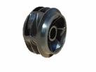
(metal) Simsite
composite
Other parts that are made from Simsite are bushings, wear rings,
casings and housings.
Even complete vertical and horizontal pumps (including 9196 ANSI are
made from Simsite material):


Power plants, marine, navy and chemical applications are the ones where
benefits can be substantial and immediate. For more information, you can email
your request to Pumping Machinery via our link Selection and
Applications.
CLICK
HERE TO SUBMIT YOUR QUESTION