PUMP MAGAZINE: Questions and Answers
(1-20)
Editorial staff
continuously updates Q&A section by adding new questions and answers, based
on our readers interest, input and feedback.
*******************************************************************************
Question 1: Does
excessive amount of air at the pump suction cause cavitation?
Answer: No. Air has
nothing to do with it. Cavitation is caused by the collapsing (imploding) vapor
(not air) bubbles. These bubbles are simply a vaporized liquid in the region
where static pressure dropped below vapor pressure. Air causes other problems,
such as air locking, and even a very small amount of it causes significant loss
of performance (head drops), but this is a different subject.
*******************************************************************************
Question 2: Can a
gear pump "lift" liquid? What is dry lift?
Answer: Yes. Gear pumps
have good lift characteristics, in the range of 5-20 feet, depending on the
particular design. Lift characteristics of a gear pump improves significantly
if even a minute amount of liquid is initially allowed to "wet" the
internals, which is often the case if a pump was tested at the factory, and some
residual liquid remains, or intentionally pre-lubed at the site. This minute
amount of liquid acts as a capillary barrier in the clearances, preventing air
from escaping back to suction during startup at lift. With no pre-lube, gear
pump will still lift, but not as good.
*******************************************************************************
Question 3: What
determines number of stages of the progressing cavity pumps?
Answer: Number of
stages depends on several factors, with the main one is total differential
pressure. Typically, a stage is added for each 75-100 psi. For example, a 300
psi differential would require 4-5 stages. Manufacturers catalog provides
different curves for different stage number designs.
*******************************************************************************
Question 4: Is it
true that if centrifugal pump runs in reverse, it will generate zero head?
Answer: No. As a rule
of thumb, a centrifugal pump running in reverse generates approximately half of
its rated head. However, such operation is very inefficient, and motor
horsepower would be much higher, as compared with half head operation of a pump
running at the correct rotation.
*******************************************************************************
Question 5: Dear Pump-Magazine: I have a question related
to the limit of the centrifugal pump operation which you mentioned in your
article "How Does Pump Suction Limit the Flow?". Normally, a pump is
selected to operate at the Best Efficiency Point or nearly so, but in your
Figure 2-1 of the article it seems that the operating range is too far from the
BEP. Could you please explain this for me?
Thanks in advance,
Ali Abbani
Answer: Dear Ali,
True, BEP is what a pump designed for, and it would be best if it
operated there. However, since the actual operating point is an intersection
between the pump curve and a system curve - the pump ends up operating all over
its curve, because the system curve changes. Imagine a discharge valve slowly
closing - the system curve (which looks like a parabola) will become steeper -
and will intersect the pump curve at lower flow. Same for the opposite - if
valve is opening - the system curve becomes "shallower", and will
intersect the pump curve at higher flow. Intersection exactly at BEP is purely
coincidental - if the discharge valve is set to make the system curve go right
thru the BEP point at the pump curve.
Now, what happens if the valve opens wide enough to get the system
curve intersect way past the BEP, at high flow? Keep in mind that a NPSHr curve
also looks like a parabola with flow - it rises sharply at higher flow, past
BEP. As it does, the NPSHR gets higher and, eventually, exceeds NPSA
(available) - thus cavitation begins.
At low flow, cavitation is not a problem, but "other bad
things" happen - the low flow becomes insufficient to "fill the
impeller eye", and becomes sporadic, pulsing, etc. - causing pump
vibrations, and even mechanical damage.
I hope this helps. If you like, there is a book available that
talks more about the subject, as well as other pump-related subjects and
questions.
Best regards,
Dr. L. Nelik, P.E., Apics
P.S. The closure or opening of the valve is not the only way to
change the system curve. For example, if a pipe becomes more clogged, the
increased friction effectively acts as if the valve is closing. Another way of
changing is elevation of the fluid level (this changes the static part of the
curve), etc.
*******************************************************************************
Question 6: Please discuss how pumping
water differs from pumping 40% Propylene Glycol. Does the impeller have to
change trim to produce the same flow and head with a more viscous solution?
Blankin Equipment
Answer: Centrifugal
pumps work best on relatively “thin” (i.e. low viscosity)fluids. The fluid
velocities inside the passages of centrifugal pumps are generally much higher
then in positive displacement pumps – and higher velocities mean more viscous
drag, i.e. lower efficiencies. Typically, centrifugals are not used above 100
cP or so, although there are exceptions. Hydraulic Institute Standards have a
chart to de-rate the pump flow, head and efficiency (which then allows you to
calculate horsepower), as a function of viscosity.
Using this chart, a new (de-rated) H-Q and efficiency curves can
be constructed. The impeller diameter is then determined as usual, using the
affinity laws.
If you do not have the HI chart, let us know, and we will get you
one.
Dr. Nelik, PUMP MAGAZINE
*******************************************************************************
Question 7: What is the effect of the
degree of saturation of dissolved gasses on NPSH? Compare 100 deg F de-aerated
water in a tank with a bladder pressured to 10 psig with a tank without a
bladder for the same temperature and pressure, with the pressure provided by,
say, a nitrogen bottle causing the water to be saturated with nitrogen.
Thanks,
Mark Walton, Entergy
Answer: Dear Mark,
There is definitely an effect. The dissolved gas changes the
molecular interaction of the liquid in which it is dissolved. Chemical
engineers are familiar with this phenomenon via Henry’s Law, and Oswald
coefficient, which relates the V/L (void fraction – the freed-up gas volume to
liquid volume ratio) as function of saturation pressure and actual pressure of
the mixture. This is not to be confused with the effect of free gas on pump
suction performance, and neither it has anything to do, directly, with
cavitation (which is caused by vaporization of liquid and subsequent collapse
of vapor bubbles). The dissolved (not free) gas affects the “ability” of a
liquid to become vapor when the pressure drops.
In practice, a good example are cooling water tower double-suction
pumps, where the incoming water has been so well aerated when passing through
the tower - that a significant amount of
air stays dissolved, and reduces the NPSHA. The NPSH margin (NPSHA-NPSHR) for
these pumps is not significant to begin with, and with air affecting the NPSHA,
the propensity for these pumps to “get in NPSH trouble” is real. As an
estimate, the reduction of NPSHA for these pumps is about 1-3 feet.
In your case, you should be OK if NPSH margin is good. Also, even
if some nitrogen dissolved in water, it will probably stay dissolved and will
not come out of the solution at the low pressure inlet areas, because of the
time delay – it flows through quickly. In the cooling tower example, the water
stays well dispersed in order to get cooled, i.e. the surface area is extremely
enlarged, and air can easily get in.
Dr. Nelik, PUMP MAGAZINE
*******************************************************************************
Question 8: I would like to more about
the following;
1)backward curved blades
2)forward curved blades
3)comparison of above
4)which is more advantageous and why?
Yours Truly,
Joseph Rajkumar
Answer: Dear Joseph,
The shape of the blades depends on the details of the hydraulic
design. A centrifugal pump operates on a principle of imparting an angular
momentum to a fluid, i.e. literally the fluid must change direction as it
passes through the impeller blade cascade. In other words, there is an exchange
of energy, as a mechanical torque is transmitted from the motor shaft to, ultimately,
the hydraulic energy, which manifests itself in building a pump pressure.
Hydraulic designers refer to this as “velocity triangles”: one at the impeller
blade inlet, and another at the exit. A velocity triangle has peripheral
velocity (U), absolute velocity (V), and relative velocity (W), as shown below,
with impeller rotating clockwise:
Figure Q8-1 “Backward-curved” blades, - most pump
impeller designs
The ability of building up pressure depends directly on product U
x Vtheta , which means that for higher pressure the impeller OD must
be larger, or the pump should rotate faster – these make velocity “U” vector
longer. The relative velocity vector (W), including its magnitude and
direction, must be such that the velocity triangle closes-up to produce the
desired pressure and flow. For most centrifugal pumps, this relative velocity
vector ends up (anti-intuitively) “backward”, against the direction of the
velocity “U”. The angle between the vectors U and W is called a relative flow
angle “beta”, and the blade angle is set approximately equal to that. This
angle “beta” ranges between 10O to 35o , for most single-stage
centrifugal pumps, but, at higher values of Specific Speed (NS), such as
turbine pumps, it can be as high as 40o to 50o
Some machinery has significant space limitations, such as car
hydraulic transmissions. There, it is not possible to “beef-up” velocity U by
large impeller OD, and the only option is to curve the blades “forward”, to
still create a large velocity Vtheta , and thus build up
the same pressure as was in Fig. Q8-1 above:
Figure Q8-2 Special “forward-leaning” blades, such as
in a pump of a hydraulic transmission
While this allows significant size reduction, the downside is low
efficiency, because the absolute flow velocity becomes too large, and would
result in increased hydraulic losses for a “normal” pump. In hydraulic
transmission, however, there is a pressure recovery turbine, which sits
immediately after the pump. The blades of the turbine wheel are also curved in
a “funny fashion”, to accommodate and match the exit velocity triangle of a
pump. Thus, the turbine “picks up and recovers” the velocities produced by the
pump.
As most pump impellers discharge directly into a volute, or a diffusor,
without having a special recovery turbine wheel following the pump impeller,
the majority of the designs have backward-leaning blades.
Explanation beyond that requires more specialized reading, and, if
you are interested, let us know for a recommendation of books on this subject.
Dr. L. Nelik, PUMP MAGAZINE
Discussion:
For a back-ward curve vane centrifugal
pump, what is the theoretically highest head achievable for a given impeller
tip-diameter and rotating speed? How is the equation derived?
Rajiv Bhatt
Answer: Dear
Rajiv,
As you can see from the velocity triangles shown above,
head rises as flow is reduced. At zero flow, the meridional velocity vector is
zero, and the tangential component of the absolute velocity is exactly is equal
to the rotational velocity (more on nomenclature see Article #13 under
Technical Papers section). This is the same regardless of the type of the
blades or their number. Thus, the equation for the idea head becomes the
following at zero flow (VTH=U):
H = (U
x VTH)/g = (U x U)/g
For example, suppose you have a 6” impeller at 3600
RPM. Peripheral (tip) velocity of the impeller wheel is:
U = 6
x 3600 / 229 = 94.2 ft/sec, and H = 94.22 / 32.17 = 276 feet
(In above, we assumed to inlet prerotation, and 229 is
a conversion constant for US units, and gravitational constant g=32.116 ft/s2)
Note also that the width of the impeller does not come
into equation either! – but only the impeller OD. (You may want to check a few
pump curves at a pump catalog for the value of head at shut-off, as a matter of
interest).
Regards,
Dr. Lev Nelik, P.E., Apics
Pumping Machinery
*******************************************************************************
Question 9: Dear Sir, I have visited and
read your website, and done as much research as I can. I have a problem and question. I am trying to pump an oil and 5 micron
slurry using a semi-open centrifugal pump. It is a 2 hp pump made by
Jacuzzi. It pumps well for about 1 hour,
and then the motor slowly starts to bind up.
When I take the impeller out, I find the slurry has packed between the
rear of the pump (where the seal is) and the impeller. The space is about 3/4
inch. This gets so hard packed, that it binds the impeller to the housing, so
the motor cannot turn it. The seals work fine. My question is: What can be done to prevent the slurry from
packing behind the impeller? I have
tried placing spacer material behind the impeller to prevent the slurry from
getting in, but it just gets ripped apart. I also tried welding small fins in
the rear to move/"push" the slurry back out. It still packed. One
idea I have not tried is to drill a hole through the impeller, as near the
center as I can. Maybe this will cause some fluid flow to occur behind the
impeller, so it will not pack. Do you think this will work? Another idea would be to drill a hole to the
back of the impeller chamber, and attach a line from the pump discharge (or
maybe the suction is better?). Maybe the
slurry fluid under pressure will prevent the packing if it is introduced to the
rear of the impeller space. Please help,
as I have almost run out of ideas.
Thank you,
Mike
Answer: Dear Mike,
Both of your ideas are good. Drilling the holes should enhance
re-circulation, and might flush out the solids, keeping them from gradual
accumulation. Attaching the line is fine too – from discharge is better, as it
would bring in a higher pressure, a stronger flush. You should put a cyclone
separator to separate the particles, otherwise they might still be getting
packed up. If you can not find a cyclone, perhaps simply connecting to a large
settling tank for particle to settle down, but take off the cleared liquid from
the higher elevation within the tank.
Or, if you can attach a separate clear-liquid line, then it should
be even better. Of course make sure the pressure is that line is high enough,
so that clean liquid goes into the pump, and not the other way around!
I hope it helps! Let us know!
*******************************************************************************
Question 10: Is there any possibility
of obtaining a hard copy of the magazine and if
so what is the procedure for that ? Alternatively, can I
find it on a CD for instance?
Best regards,
Dr. A. H. Sadka,
Answer: We would be
happy to send you a CD. At this time, a hard copy would be a printout in a
binder. Let us know which version you would like.
PUMP MAGAZINE
*******************************************************************************
Question 11: I discovered the PUMP
MAGAZINE site this morning, and I would like to know if there is an actual
(hard copy) magazine. Our company manufactures gears and gearboxes, and other
products. We have several customers who are involved in pumping, and needless to
say, we are interested in expanding our customer base and knowledge. We would
be interested in advertising in your magazine, and how to go about it.
Best regards,
Christina Vukovic,
Answer: Dear Christina,
We would be glad to assist with your request to advertise in the
PUMP MAGAZINE, and have passed your note to our logistics people to contact
you.
Dr. Nelik, Editor, PUMP MAGAZINE
*******************************************************************************
Question 12: Dir Sirs, I must
congratulate you for starting this very useful site. Can you give me some guidance for the
permissible level of shear stress in pump shafts used for double suction split
case pumps for the following materials: ANSI 410, 431, 316 ?
Thanks and regards,
Himadri Sen
Answer: Dear Himadri:
Allowable stress levels, for static components, are usually
related to the tensile stress of the material, per ASME rules. For
cyclically-loaded components, such as shafts, the endurance limits are applied,
which produce values more conservative then for statically loaded members. For
example, martensitic stainless steels, such as 400-series, often have a value
of 7500psi allowable, but each manufacturer may have its own values and procedures.
The importance of knowing the allowable shaft stress is obviously
to determine if a shaft diameter is sufficiently large. However, other factors
need to be considered. For example, for the types of pumps you mentioned, the
impeller can be positioned on a shaft axially in variety of ways. Some designs
have threaded shafts, with locknuts against the impeller hub. Others may have
lock-rings, positioned in a shaft groove. Threaded shafts present additional
stress concentration - and the shaft
diameter must be sized even more conservatively to accommodate that. For double
suction pumps single-stage pumps, the impeller sits in the middle of a
between-the-bearings span, and if the shaft is threaded, the threads end up
also close to the middle of the shaft, where stresses and deflections are
highest – not a very desirable situation.
If a sleeve positions an impeller axially, and threading of the
shaft is thus eliminated, or removed further away from the center of the shaft,
this would be a better design alternative. You may look up the cross-sectional
illustrations from several manufacturers, to compare the designs, and how the
impeller-to-shaft positioning is accommodated.
Regards,
Dr. Nelik, PUMP MAGAZINE
*******************************************************************************
Question 13: Dear PUMP MAGAZINE,
Thanks for your prompt reply for my earlier query (editor: see
Question 8). I would like to know how a gear pump or any positive
displacement pump develops pressure.
What is the volumetric efficiency of Pumps and what
range is it in percentage for any pump-centrifugal? What is the range of
mechanical efficiency for a centrifugal pump?
Thank you.
With regards,
Joseph Rajkumar
Answer: Dear Joseph,
You can think of centrifugal pumps as – “pressure (or head)
generators”, and positive displacement (PD) pumps as – “flow generators”.
PD pumps displace a certain amount of fluid, carrying it from suction port – to
a discharge port. PD pumps do so against a given system pressure. Thus, with
each revolution of a shaft, a PD pumps displaces a given amount of fluid, which
is why they are often compared by the GPR (gallons-per-revolution), or cc/min,
or similar units. This is why PD pumps can meter the flow, although some
types do that better then others. Since they move fluid against the
differential pressure, that very pressure causes some of the fluid to “slip
back”, i.e. escape from discharge side to suction side, through the internal
clearances. This “slip” depends on clearances, viscosity, and differential
pressure. The ratio of the net flow (ideal flow minus the slip)to the ideal
flow (if there was no slip), is volumetric efficiency.
In case of cetrifugal pumps, the flow also slips back, through the
impeller clearances, and is called leakage. Centrifugal pumps can not handle
appreciable viscosity fluids (usually under 50-100 cP), i.e. water-like, so the
leakage is important for these. PD pumps, historically, have been used for more
viscous fluids, and, since there is almost no slip because of that, the
volumetric efficiencies are rarely discussed, or even plotted.
For both types, performance curves include either total
efficiency, or power (one can be easily calculated from another, for a given
flow and pressure (or head). Total efficiency includes all three components of
losses: volumetric (slip or leakage), hydraulic (friction), and mechanical
(seal friction, bearings friction, coupling losses, etc.).
Some PD pumps can handle thin fluids better then others. For example,
certain gear pump designs exit to handle chemicals, such as sulfuric acid,
caustics, and the like, with viscosities under 20 cP, and often even thinner
than water (under 1 cP). They have special combination of internal materials,
to ensure no galling (seizure of gear within the housing in the absence of good
lubrication), - but, that is another subject.
Best regards,
Dr. Nelik, Editor, Pump Magazine
*******************************************************************************
Question 14: Dear Sir,
I would like to know more about positive displacement
pumps, such as its functions, major components, typical applications and common
defects. Most of the websites related to this are advertising products. Is
there a website you can recommend? Thank you.
Yours sincerely,
Devaraj Subramaniam
Answer: Dear Devaraj:
Interestingly, a previous reader asked a similar question (see
Question #13).
There are two classes of pumps: kinetic (centrifugal), and
positive displacement. Each has several sub-classes, as classified by the
Hydraulic Institute. PD pumps have reciprocating and rotary sub-classes. For
example, rotary are: gear pumps, 2 and 3-screw pumps, progressing cavity
(single screw), lobe, etc.
Each has advantages and disadvantages. Obviously, the subject,
overall, is too wide to cover in a short note. There are books we can
recommend, for example "Centrifugal and Rotary Pumps: Fundamentals and
Applications", by CRC Press, 1999, Dr. L. Nelik - you should be able to
track it at your local bookstore computer system, or call CRC at Boca Raton,
Florida. There are also courses and training seminars available, and I can
recommend some if you are interested.
What types of applications do you have? Perhaps we can recommend a
pump type, if you get us some more details,
Sincerely,
Dr. Nelik, Pump Magazine
*******************************************************************************
Question 15: Hi,
How important is the hardfacing requirement below the sleeve
bearings in the 416ss shaft of condensate pump? The condensate pumps are having
carbon bearings. During initial start up it has been proposed to use
sacrificial bronze bearing when fine abrasive contaminants are expected in the
pumped liquid. There is of course 1/16" perforation strainer, but fine
abrasives still pass. However, during normal operation the liquid will be free
from such nuisances.
I am asking this because hardfacing seems to be very
costly and it appears to me that it may be effective, if at all, during start
up only.
Please advise at your earliest.
CHANCHAL KUMAR NATH
Bechtel, India
CW-32-SF, Malibu Towne
Sohna Road, Gurgaon
Tel: 91-124-6219516/9517
Answer:
Dear Chanchal,
 It is really a
matter of expense and convenience. I assume you have a Vertical Turbine type
pump, such as, 316ss, 17-4PH, Monel, etc. Sleeve type bearings are provided at
each stage to assure stable operation away from critical speed. Condensate is
usually hot, and water, which does not have good lubricating characteristics to
begin with (as compared with oil, for example), does not develop a stable
hydrodynamic film to support the shaft. For this reason, carbon bearings are a
good choice, because carbon has good self-lubricating properties.
It is really a
matter of expense and convenience. I assume you have a Vertical Turbine type
pump, such as, 316ss, 17-4PH, Monel, etc. Sleeve type bearings are provided at
each stage to assure stable operation away from critical speed. Condensate is
usually hot, and water, which does not have good lubricating characteristics to
begin with (as compared with oil, for example), does not develop a stable
hydrodynamic film to support the shaft. For this reason, carbon bearings are a
good choice, because carbon has good self-lubricating properties.
However, when abrasives are present, the shaft, and especially
bearings (carbon is soft) wear out. To combat this, shaft is hard-coated, and
better wear-resistant bearing materials are used. Leaded bronze, known
Asarcon-520 was used for marine applications, to better resist abrasion (it
also a good cavitation-resitant material), or hardened nickel-plated shafts are
also known to work. Bronze works too. Torlon was known to replace bronze in
centrifuge applications (these are much slower running and tougher then pumps)
at 40 to 600 RPM.
PEEK (polyetheretherketone) line bearings were found to work very
well in abrasive applications, and could be a good candidate here, because of
elevated temperature rating as compared to some other engineered plastics.
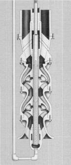
When abrasion problem is continual, rifle drilling of bowl shafts
can used for bearing protection against abrasives, as shown on the picture
above (Goulds model VIT), but such flushing is probably an overkill for your
case, since you expect this to be a temporarily problem, until your new system
gets flushed out and debugged.
So, we are back to economics and convenience. I think hardcoating
of the shaft will pay off, if it saves the otherwise softer shaft from frequent
replacement. Bronze bearings probably will wear out faster then PEEK, but if
you expect system to become clean soon, - this may be OK. Otherwise, if running for extended time with
abrasives, bronze bearings wear out and clearances open up, - then the shaft
vibration may become a bigger issue then you want it to be. The added headache
of pulling out the pump and replacing bearings and/or shaft is expensive also.
I hope this helps, - let us know how it works out,
By the way, I suggest you conduct periodic measurements of pump
vibrations, which could give you an indirect warning of the wear.
Luis Rizo, Pump Magazine
*******************************************************************************
Question 16: I have
written several papers for the European Journal of Physics on various historically
important and interesting machines (such as the Watt steam governor and the
pendulum clock). I now plan on writing a similar paper on the rocking beam
('nodding donkey' or 'grasshopper') pump. Can you point me in the direction of
any technical articles, web addresses, journal references, engineering
textbooks or historical articles relating to these machines?
Regards,
Dr. Mark Denny
Answer: Unfortunately,
I am not aware of articles or material about such pumps, although I am sure
there must be many. However, whenever I travel to Texas, Louisiana, etc. there
are numerous installations of these pumps, pumping oil from wells. I can refer
you to a good pump distributor that I know in Texas, and perhaps they can
suggest some sources you can go to, to get info. E-mail to Tom Manis,
Progressive Pumps Company: ppumpco@aol.com, in Houston.
Best regards,
Dr. L. Nelik
P.S. If I come across something on this subject in the future, I
will certainly let you know. Also – if any of our readers can help – please let
Mark know.
*******************************************************************************
Question 17: Dear Dr.Pump
I would be very grateful if you could provide me
information regarding tests done by pump manufacturers and related Codes and Standards.
Is it only creating Q versus H diagram, and other parameters calculated
theoretically? Please advice me, thanking you in advance.
Yours truly,
Keyhan Nouriafshar
Answer:
Dear Keyhan,
Hydraulic Institute is a known and respected authority on pump
standards, with comprehensive description of tested and derived data, accuracy
and tolerances. HI covers centrifugal and positive displacement (reciprocating
and rotary) pumps, and you may want to obtain a set if you indent to refer to
it at times. I believe you can purchase the whole set, or individual sections
only, depending on your needs. If you have trouble locating these, and just
have a one-time-need-to-know of a specific topic, let us know, and we will try
to help.
Typically, for centrifugal pumps, tests include performance
and NPSH. For performance, a discharge valve is throttled, changing the
pump flow and pressures, which are recorded. Torque meter (between the pump and
a motor) is recorded also, or, if a calibrated motor coupled directly, a
horsepower can be read directly, or calculated from current, voltage, etc. Pump
head is then calculated from pressures, with adjustments for the velocity heads
and gage elevations.
For NPSH, a pump suction valve is throttled (or a vacuum tank
pressure is changed), reducing the suction pressure. Eventually, pump
differential pressure begins to change, and, when it changes by 3%, the NPSHR
value is obtained.
The plotted data usually contains Head, Power and Efficiency,
plotted against Flow. For NPSH test, NPSHR is plotted against Flow.
For positive displacement pumps, the plots have flow versus
differential pressure. The slope of the curve (usually a straight line)
indicates the deviation from “theoretical” flow, and is called a “slip”. Slip
depends mainly on differential pressure, viscosity and internal clearances. For
metering applications (where PD pumps are especially good), the slope is much
less, due to attention to internal clearances.
For more information on pump curves (centrifugal and PD) see
numerous articles in Pump Magazine (section Articles).
Best regards,
Lev Nelik, Pump Magazine
*******************************************************************************
Question 18: Hi
there,
I need your advice whether I can use air-operated
double-diaphragm pump (Wilden) for the following liquid:
Pumped fluid: Ethyl Mercaptan (LPG Odorant)
Flow: 82 GPM
Discharge pressure: 46.8 PSI
Suction Pressure: 17.2 PSIG
Differential pressure: 29.6 PSI
Specific gravity: 0.84
Viscosity: 0.29 cP
% solids size : None (clean)
Preferred construction : Pls comment
Thanks,
Faiz
SECA DYME SDN BHD, www.seca-dyme.com
Answer: Dear Faiz:
Widen offers metal construction pumps, as well as plastic
construction. Mercaptan does not have good lubricating characteristics and very
“thin”: 0.29 centipoises is even thinner than water! The main issue with
pumping thin fluid with positive displacement pumps is slip, as it becomes
difficult to make internal clearances extremely tight. For gear pumps it is
diametral and lateral clearance between gears and casing, and for diaphragm
pumps it is a clearance between the balls or flaps of the internal valves,
which is a challenge. However, for small differential pressures, as you have,
the slip would not be excessive, and the pump should work fine. Below is a
curve from Wilden catalogue for their “T8” model. The dot indicates your
conditions: 80 gpm, 30 psi. Following the curve, the air pressure needs to be
60 psi, and 60 SCFM air consumption.

I also looked up your web site to see where you are located. In
Lev Nelik, Pump Magazine
*******************************************************************************
Question 19: I want to use a Grundfos
Type LP 100-160 42 F 300 model C pump to supply a
large water feature in a large garden (ambient
temperature 20 to 25 degrees C, fresh water). The Head on the ID plate is 34m
but the height of the outlet above the pump would be only 4m. Water would be
pumped through 20m of 110mm poly pipe to reach the outlet. The pump would be
positioned approximately 250mm below the level of the supply water with less
than 1m of 110mm pipe between the source and the pump inlet. The calculations I
have done suggest that the
pump would have ample supply to prevent cavitation.
However I am wondering what the effect on the pump would be by only lifting the
water 4m on the outlet side. Would this create a problem? If 'no' can you take a guess at what the output
rate would be? If 'yes' can you suggest
any possible fixes?
Would you agree that the supply side is not a problem? I
have attached the information that appears on the pumps ID plate and the data
sheet that was sent to me by Grundfos in Australia. This data sheet is for an
LP 100-160 168 even though I told them that my pump was an LP 100-160
42 F 300. Could you possibly confirm that both these
codes represent the same pump and that the data
I have is applicable?
In case your are wondering: I did originally ask
Grundfos tech support if they could answer these questions and they could not.
I realize that these questions are probably outside of the normal scope of
requests but I really would appreciate any help you can give me.
Kindest regards,
Hans Andersen, Australia
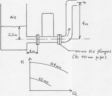
Answer: Dear Hans, - we
tried to picture your setup as you described it (did we get it right?):
Grundfos has a nice web site (www.grundfos.com),
although their SEARCH feature seems to limited, and “nothing found” message
pops up. However, after some round-about searching through their site, we found
a description of the pump, and some “hints” on the rest of the code. Their LP
model is a single-stage vertical centrifugal pump. The full cataloged
description of your pump model appears to be: LP 100-160/168 A-F-A-BBUE. This
means 100mm flanges, with nominal impeller diameter 160mm, with actual
installed diameter after the “/” (max available 168mm). “A”=pump version, and
“F” stands for DIN flanges. Next “A” is for material code, with “BBUE”
describes the seal code. Your own records indicate LP 100-160 42 F 300, which
is probably what they stamped on the nameplate of your (overstock?) pump, or
what might have come with the original (way back?) documentation. This probably
means 42mm actual impeller diameter (although the missing “/” could be
confusing), and the F300 is the motor flange. (By the way, LP means 2-pole
motor (2950 rpm for Australia) – the 4-pole would be LM).
Now, let’s talk hydraulics a bit. The pump-generated-Head is the
difference between elevations, friction losses and velocity heads. If we
reconstructed your application description correctly, the difference in
elevation (static head) is 4-2.5 = 1.5m. Since piping is the same diameter on
both sides, there is no correction for velocity heads. The friction losses are
unknown, since we do not (yet) know the flow, but let’s assume, for now, there
is another 0.5m in friction losses. So, the pump needs to produce about 2m
(H=2m). From the Affinity Laws, the Head is a function of the square of
impeller diameter. According to Grundfos catalog, shut-off head is about 40m at
168mm impeller. To produce 2 m, it would have to be cut by: sqrt(2/40)x168 = 38mm
The affinity law needs correction after trims over 10%, which is
why impeller actually is 42mm.
If you now look at the curve, the flow would be around 20-30 m3/h.
You could now make a more accurate calculation of head, accounting for friction
(now that you have the flow), but it will probably be roughly at the same
ballpark. (I suggest you measure your impeller OD, to make sure).
Regarding suction, it looks OK. I assume your inlet tank is open
to atmosphere? If so, your available NPSHA is about 10.4m+2.5 = 13m. You need
to correct that by suction velocity head, friction losses and vapor pressure
(see discussions on these topics at other sections of Pump MAGAZINE), but you
still would end up around 12m or so. Grundfos shows NPSHR (required) under 4m at
max. impeller diameter and way at
run-out flow. When impeller is cut (especially as much as yours: 42/168 = 77%!
– a lot!), NPSHR gets worse, - perhaps to 3-5m, but most likely still
sufficiently below the available.
One thing you need to watch out is air vortex at the inlet.
Depending on the actual tank, or sump, details, the air could get “sucked-in” –
not a cavitation, but another nasty thing for a pump. Hydraulic Institute has
charts, illustrations, and formulas for the suction designs, and you may want
to look at that. We also touch on this subject in other areas of the PUMP
MAGAZINE. However, from a first look, it seems like you should be OK on the
suction side.
Regarding manufacturer Tech Support inability to help you – we
sympathize. Sometimes, going to your local pump distributor is a better idea.
Manufacturers are usually “insolated” from the end users by the layer(s) of
distributors, and sometimes are either too remote, or too big, to be able to
assist. A good local pump distributor may be a better source – plus, they would
unlikely recommend a pump “5-times the size” of what you need! We are not sure
of your exact location in Australia, but you may want to give a call to Process
Pumps PTY, Ltd - in Sidney (61-2-9605-9130) or Boronia (61-3-9762-9222) – a
technically strong and established pump distributor, - they may be able to help
your with your local pumping needs.
I hope this helps, - and good luck! – Let us know how it works out
for you!
Dr. Lev Nelik, PUMP MAGAZINE
P.S. You may want to check out the Quiz section of the PUMP
MAGAZINE, for more hydraulics training.
Reader’s follow-up:
Dear PUMP MAGAZINE,
Firstly, please allow me to pass on my sincerest thanks
for your prompt reply to my enquiry. It is indeed a pleasant surprise to receive
such quality service.
There are a couple of points I would like to follow up,
if I may. Your drawing of the intended application is pretty close however the
distance of the pump centre line to the surface of the supply water will only
be approximately 250mm not 2.5m. You see the supply water will be filtered from
a large pond located at the base of a waterfall. As you can guess the intention
is for the pump to drive that waterfall. At this stage I haven't looked into
controlling the problem of air vortex as I'm still trying to establish the
suitability of this pump. I want to achieve the greatest possible flow rate in
order to create the most impressive waterfall I can.
Also I have checked the OD of the impeller and it is
168mm. Given the maximum size of the impeller how would this effect the flow
rate over the reduced elevation of only 4 metres. I guess what I am asking is
how do I achieve the flow rate of 125m3/hour with only 4 metres of elevation?
Is this possible?
Kindest regards,
Hans Andersen.
Response: Dear Hans, -
you are correct! – our mistake! – 250mm is indeed 0.25m! And now things are
“getting interesting”! The water level is now barely over the inlet pipe: 250mm
– 110/2 = 195mm. The good news is you have verified the impeller diameter,
168mm, so that at least we are passed the issue of nomenclature. Goes to show –
when in doubt – measure! It is not a problem now to reach high flow, as this
pump BEP is at 100 m3/h at 34m head. If you run-out a bit beyond the BEP, you
should be able to get to 125 m3/h. But what seems to puzzle you is how to
reconcile the 34m head with only 4m elevation?! Well, a Quiz is to the
rescue! Take a look at the Quiz section of the PUMP MAGAZINE – it shows
something similar to what you have, doesn’t it? This is how: a system curve is
a parabola, with an offset up the H-axis by the “static” head (not a function
of flow) of 4m, and the rest is friction (depends on flow). A pressure drop
across the valve is another form of a hydraulic loss, and is too a function of
flow. The intersection of a system curve with the pump curve is a pump
operating point.
But back to the suction: with suction now barely covered, and – a
“hurricane of flow” (check the velocity head and do not forget it in NPSHA
calculations!) – you may have trouble. First, you may be getting too close to
NPSHA limit, but mostly – air entrapment could be a real issue – and – with a
huge shallow pond of water – there is a lot of air dissolved in the water too!
What you may want to do is some sort of a localized "en-Dome-ment"
(if there is such a word!), to artificially raise the water level locally by
the pump suction, to keep the air vortex from being sucked in. Hydraulic
Institute has a very good section on suction sump design, and you may consider
looking at that.
Again, you local pump distributor (we sent a note to one, to check
your Question on our web, and by now they probably have read this response too)
may be of help, - they usually carry HI books on their shelves. If not – let us
know – and we can help you.
I hope this helps! Send us a photo of your beautiful fountain once
the “bugs are out”!
Regards,
Lev Nelik, PUMP MAGAZINE
*******************************************************************************
Question 20 – submitted via Help-to-Select-A-Pump
section:
Name: Dave Pichotta
Pumped Fluid: 60%/40% mixture of bird seed and animal
fat
Flow: 6 to 8 GPM
Discharge Pressure: <50 lbs
Suction Pressure: 2-3 ft of head
Differential Pressure: ?
Specific Gravity: ?
Temperature: 120 degrees F
Viscosity: Animal fat 1000cps seed portion ?
% Solids and Size: 60% solds .0626 to .375 inches
Preferred Materials of Construction: stainless
Comments: Would a rotary lobe pump work to pump this slurry?
I have used progressive cavity pumps with poor result. Volumetric Piston Pumps
work but service and repair are issues.
Answer:
Dear Dave,
A Rotary Lobe pump should work, although it should be sized large
enough to accommodate solids, and to run slow (probably under 200-300 RPM) due
to high viscosity and solids. Pump life generally is inversely proportional to
RPM^3 (cubed), especially if solids are abrasive.
Rotary Lobe pumps and Rotary Piston pumps are similar. Piston
version (such as manufactured by Waukesha) has two pistons, and Lobe design
usually has three lobes. Both types generate smooth, non-pulsing flow, with
little impact on shear sensitive fluids, which is why they are often used in
the food industry.
What was the problem with PC pumps though? Usually, they are also
good for handling solids – but do not run them dry! – perhaps that was an
issue? Also, PC pumps have differently sized rotor-to-stator clearance
dependent on temperature, because the elastomeric stator expands inward, into a
metallic rotor, increasing friction significantly and causing failure (rubber
“chunk-outs”). A double, or triple clearance designs may be needed for higher
temperatures, as well as lower speeds.
What was the MTBF for your PC versus Rotary Piston design? You may
need to look at your system, regarding dry-running possibility for the PC case,
or too high RPM for the Piston design case. If so, the Lobe pumps may exhibit
same issue.
Lev Nelik, Pump Magazine.
e-mail
your questions, comments and suggestions to us at:
CLICK
HERE TO SUBMIT YOUR QUESTION