 Pump
Magazine On-Line
Pump
Magazine On-Line

INDUSTRIAL DIGEST
|
INDUSTRIAL DIGEST
|
|
|
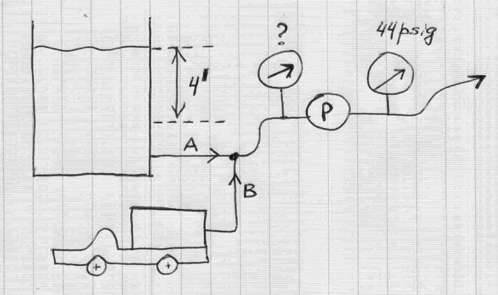
Article #60: SEEING IS BELIEVING? - NOT ALWAYS! - A TRICKY SUCTION GAGE STORY... (Published initially by the same author at Fluid Handling Systems - Plant Maintenance Magazine, April 2003 Issue) I got a call from a plant operator in Ohio: "Lev, we are going crazy here...I know we are getting the right flow from our system, but the gages are driving us nuts! What's wrong?" "Wait a second, Steve...Slow down here. Tell me more about this, - and let's see the details", - I knew Steve from our past work together. He was an experienced mechanic, but had little tolerance for time, although, knowing that his boss is probably on his case, I could not blame him for wanting the answer before I even had a chance to understand what was going on there. "Well, here is a thing. We got a big contract from the customer, to supply a bunch of oil heating systems, and have just completed the first unit, and ready to ship it. These are mobile skids with a centrifugal pump, transferring oil from the tank to the filling containers. We designed the system for 30 gpm, and tested at the shop test facility. But when we set it up on a mobile unit and hooked up the suction line to the supply tank, we are getting funny results" I reached for the paper pad, and started to sketch up the system: "Steve, tell me about your system. What type of pump do you have?" "We got Goulds' 1x1.5-6, with a 5.12" impeller OD. We are pumping oil through the heat exchanger, to fill containers. The whole thing is mobile, and we have a short suction pipe, which the customer hooks up to the large tank to supply filling stations. We sized the pipes large, especially suction, to make sure friction losses are negligible. We intend to test each unit at the shop, using our shop flow meter, but in the field there will be no flow meter (these things are expensive!), and they would need to estimate the flow rate based on the pressure gage reading. Each unit come with a certified pump curve, so estimating the flow from pressure should not be a problem" That sounded simple enough, and I scribbled a simple sketch while listening:
Steve continued: "I know we are getting 30 gpm - I calibrated our shop flow meter myself, and recalibrated the darn thing again, to make sure! The discharge gage reads 44 psig, which converts to about 118 feet (our oil is 0.86 specific gravity). If I use this number, and look-up the flow at that head from the pump curve, I get about 30 gpm" "So, what's the problem, Steve? You get the right flow, and your gages measure the pressure which corresponds top the same flow per pump curve. Sounds good to me! I assume the suction gage reads about zero, so that the 44 psi you are talking about is differential across the pump? Then - what's the problem?" "That's the whole thing, Lev - the problem is that the suction gage shows about 7 psig. If it read about zero - I would be happy. But this way the differential is 44-7 = 37 psig, and that - if you look at the curve - would read nearly 80 gpm! If not for the fact we need to start shipping these units, - I would be applying for a patent for a perpetual motion machine!" I jotted the numbers down - Steve was right, the head corresponding to 37 psi differential was 37x2.31/0.86 = 99 feet. I reached out and pulled up a Goulds pump catalogue - sure enough, at 100 feet the 1x1,5x6 pump with 5.12" impeller should be pumping 80 gpm. Was his meter wrong?
"Steve, let's see - can tell me a bit more about the suction side?" "Well, it's simple. We got a tank, which is always filled, about 4 feet level above the pump inlet, - I know about the air entrapment! - and designed the tank myself, to make sure no air drawn in. I even looked inside - the surface is nice and smooth, - no vertices". "Hmm... You are right, it does sound funny... Listen, - let me think about this for a few minuets, and run some numbers, and I will call you back". "OK, Lev. But please call as soon as possible. I need to get this resolved" "No problem, let me call you right after lunch - you go eat and relax, cool off, by friend, - and I will do some thinking in the meantime". I hung up and re-did the numbers. There was no smoking gun..., - but wait! Didn't he say the tank level was 4 feet? If so, that is only 4x0.86/2.31 = 1.5 psi, - and, with even small losses on the suction side, the gage should read even less - perhaps 1 psig, but certainly not 7 psig! Where did the 7 psig come from? I had to call him right back, - Steve was still there, and knowing him, I figured lunch was not on his agenda today. "Steve, I bet what funny is - the suction pipe! - you must have either a short elbow, or even a few of those, in front of your pump!" "Well, yeah... You don't have much room to maneuver there, so we had to get creative, to turn the piping around. Why?" "I think what you got is suction swirl, which is created when sharp radius elbows are too close to the pump inlet. You get the right flow - but the suction gage registers higher pressure, - it picks up not only purely static pressure, but a dynamic, rotating, component. The result - artificially high reading of the suction gage - in your case, 7 psig. Also, your pump BEP (best efficiency) point is about 90 gpm at this impeller diameter, and you are operating at 30/90 = 33% of BEP. When a centrifugal pump operates at low flow, there is a thing called "back flow", which is a swirling flow actually leaving the impeller tip and moving backwards, in a rotating pattern. That also adds to a suction gage reading". "Darn it! That simple? But what do I do to fix it?' "Two things. First, you should try to straighten the suction piping by eliminating elbows, or at least to insert the flow straightrenerns. There are devices like that on the market, to keep the flow "straight". Another thing is..." "I know, I know! - put another straigtener between the gage and pump inlet?" "Yes, that will work. If you install a honeycomb, or a simple cross-member between the suction gage and a pump - the "backflow" would be "broken down", and a swirling component will disappear in front of the gage - and it will read what it needs to read: about 1 psig, or so." "Gee, thanks! Let me get working on that, and I will let me know how it worked out. I hope you are right" "Please do. By the way, one more thing. Since you understand what is going on, - why change anything? What you can do is simply except the fact that suction gage should be (although it does not) reading approximately zero. Then, make up a calibration curve, plotting pump flow versus discharge pressure. Do that at your shop, where you measure the flow. Then, the customer would simply read the discharge pressure (no suction reading), and read the flow off the curve. Not a "clean way", but should work!" "Hmm.. I guess you are right. Let me talk to the guys here, and see what they say. I still want to test your "anti-swirl" idea, just to make sure!" After he hung up, I knew his mind was now on testing the suction "backflow" effect. Steve likes to prove things. He did, and called me back in a few days. He sounded much better. The swirl theory was right. Steve was happy. And, judging from the fact that he shipped the first several units already, so was his boss. Sometimes "seeing-is-believing" may not be as sure as it looks!
Dr. Lev Nelik, P.E. Pump Magazine Publications May, 2003
|