Article #59: INTERMITTENT SEAL LEAK IN LPG PUMP
by
Sourav Kumar Chatterjee
Manager Rotary Equipment
HPCL Plant, Mumbai India

Introduction
In a process plant industry the reliability and effective
availability of equipment are prime requirement to have high productivity and
for rendering faithful service to the consumers. The reliability of equipment
must be ensured, and could probably be estimated as following:
By proper equipment selection - 60%
By proper installation - 15%
By proper operation and maintenance - 25%
The following case study describes reliability problem with
a LPG handling pump in a field, and the way it was trouble-shooted and fixed.
History:
These pumps were installed and commissioned in March 1999.
The mechanical seal started to leak intermittently at the interval of 45-60
seconds. This problem was persisting even after increasing the RO (restrictive
/ regulating orifice) size to 5mm from 3 mm.

Figure 1 Plan 11 (includes the orifice) to provide the seal flush, and Plan 61 to cool the box. Cooling water was not provided initially.
Per manufacturer’ notes, the estimated pressure in a seal box is approximately 90% of the discharge pressure, hence (0.9 x 16) is approximately 14 kg/cm2(g).
Service: LPG
Pump manufacturer: Khimline Pumps, Ltd
Capacity: 76 m3/hr
Rated Head: 173 m
Suction pressure: design = 8 kg/cm2(g); min = 7.0 kg/cm2(g); max = 10.5 kg/cm2(g)
Operating temperature: 50 deg. C
Vapor pressure:
6.8kg/cm2(g) at operating temperature of 50 deg. C
Sp. Gravity: 0.56
NPSHA: 2.5 m
NPSHR: 1.9 m
Radial bearing: NU-310
Thrust bearings: 7310 back to back
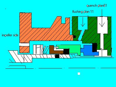
Figure 2
Durametallic (PBR, rotary bellows seal) mechanical seal, single with viton
elastomers. The seal balance ratio is 70% and pressure gradient factor for the
liquids with low specific gravity is 0.3.
The spring pressure 0.45 kg/cm2, per manufacturer notes.
Face combination: Carbon/SiC
The axial hole at the bushing was not present originally (see discussion later).
Flushing plan: API Plan 11 (3 mm orifice) and provision for cooling water plan API 61. However, cooling water was not supplied originally, and connections F/D remained plugged
Observations at site
Seal was leaking intermittently
Suction pressure: 7.5 kg/cm2(g)
Discharge pressure: 16 kg/cm2(g) (steady)
Motor load: 55 amps (steady)
Vibrations: 6.2
mm/sec max
Suspected probable
causes of intermittent seal leak:
1- hung up rotary head assembly.
2 - distortion in seal faces.
3 - axial float in rotor.
4 - seal chamber pressure below vapor pressure and liquid flashing into vapor
Observations after dismantling
A) Shining marks observed on carbon face. Rotary face found good and intact
B) Elastomers found in good condition
C) Both bearings found good and intact. No axial float observed in the rotor.
D) Impeller found intact.
E) Axial movement of rotary unit found unrestrained and free of sticky deposits.
F) Seal faces checked for flatness found ok.
G) It was noticed pump impeller has back wear ring but no balancing hole was provided.
Analysis
· As the rotary head assembly found free on sleeve, item #1 was ruled out
· Seal faces flatness found within 2 bands - hence item #2 was ruled out
· No axial float observed in the rotor – item #3 also ruled out
· The shining marks observed on carbon face revealed that, there is a loss of lubricating film on the mating faces which could be due to the formation of vapors in the seal chamber which were not getting out from the chamber due to the (too) close clearance in the throat bush. This accumulation of vapors may be due to the heat generated at mating faces and dead-ended sealing chamber. The seal chamber bush clearance appeared to be insufficient to flush out the liquid vaporization due to heat generated by the seal faces, - especially due to the fact that cooling water initially was not supplied.
The fact that the seal was failing intermittently with periodic opening of seal faces and release of LPG in to atmosphere seems significant. This could be happening because the accumulated vapors (due to phase change from liquid LPG to gas) would gradually increase in volume filling out the seal chamber, and then, when the pressure would build up sufficiently, the faces would open up, causing vapors release, and the cycle would repeat.
Applied solution
and recommendations
At first, changing to Plan 13 was considered. For LPG / Propane services, which have a narrow margin between suction pressure and vapor pressure at operating temperature, seal flushing Plan 13 was thought to take the excessive built-up vapors from the sealing chamber back to suction. This plan would consist of flush line from the seal chamber through R.O. (flow regulating orifice) to suction. However, it was decided that this would not solve the problem of vaporization in the seal chamber, because the seal box pressure would then be even lower then with using Plan 11, and thus even less margin between the box pressure and vapor pressure. Thus Plan 13 idea was rejected.
The history of attempted modifications:
Step 1 Since the in LPG service (seal chamber pressure, and the heat generated by the rotating seal faces is so close to vapor pressure) it is important to dissipate the heat generated at seal faces to avoid rapid vapor formation at seal area. Initially it was assumed that this was due to vaporization inside seal box. The orifice size was increased to increase seal box pressure. Unfortunately, this did not solve the problem.
Step 2 The API 610 8th Edition cooling
water Plan 61specifies the “tapped
connection for purchasers use. Typically used when the purchaser provides fluid
(steam, gas, water etc) to an auxiliary sealing device”.
This was initially not connected, as the location didn't have cooling water available. This was discussed with manufacturer, pointing to the fact of the LPG service may be sensitive to heat generation in the seal chamber. The manufacturer felt, however, that the pump may not require additional cooling, and so the provisions for the cooling water availability were not made. With a problem persisting, this then needed to be addressed, and cooling water circulation through sealing chamber jacket was then provided, by hooking up the inlet and outlet line to distanced headers of the neighboring unit, without the need to dismantle the pump. Unfortunately, this did not solve the problem either.
Step 3 A 5 mm hole was drilled in the throat bushing, at the upper portion of it. At the same time, the impeller four balancing holes were also added, as it was discovered upon disassembly and examination that they were missing. This modification worked, and the pump is now running satisfactorily without any leak.
The seal box pressure for this type of a pump (after
modification with back wear ring and balancing holes) is suction pressure +35%
of discharge pressure as per manufacture’s rule of thumb for the light
hydrocarbons:
8.0 kg/cm2 + 0.35% x 16 kg/cm2=13.6 kg/cm2 (g)
Interestingly, this is almost equal to box pressure before modification (as used by the “90%-rule” calculation above). Hence, theoretically, this modification does not change the seal box pressure substantially. What changes, however, is the amount of liquid from the discharge connection to the box, and then through the opened-up bushing. In other words, the restrictive factor was the bushing clearance and not the orifice in the Plan 11 piping.
Hence by making the hole in throat bush and adding balancing holes, the passage for circulation of fluid carrying out frictional heat, became less restrictive, and solved the problem, without excessive downtime and cost. From our experience, we feel that light hydrocarbon service pumps, with narrow margin between vapor pressure and suction pressure, should be provided with a 3-5 mm drilled hole in throat bushing at the top portion to allow the vapors to vent away from the seal chamber.
For comments and feedback on this Field Case, please e-mail to: