By
President
Pumping Solutions, Inc.
Progressive cavity (PC) pumps are self-priming rotary positive displacement pumps with smooth output flow. They are capable of pumping both thick and thin fluids, and do very well at pumping liquids with high solids and abrasive content. These capabilities have made the progressive cavity pump THE pump of choice for many applications in the wastewater treatment industry.
In recent years, advances in pump design, electronic monitoring, and materials of construction have allowed the PC pump to handle more severe application conditions, while at the same time improving the pump’s energy efficiency and decreasing maintenance requirements.
The purpose of this article is to give a basic overview of the pumps operating principle and review some of the new technical innovations that end users might be able to benefit from.
Rene Moineau invented the progressive cavity pump in
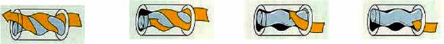
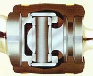
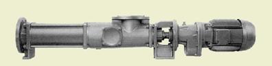
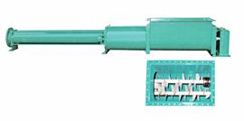
The PC pump is made of three major sections:
(Courtesy
In recent years many improvements have been made in these three areas to improve the pumps overall performance.
Improvements
in drive train design:
|
Features |
Benefits |
|
Close
coupled or Block Design |
Smaller
pump package Less
Upfront Cost No
drive alignment issues Eliminates
the need for safety guards |
|
Easy
|
Simplifies
seal service, reduces down time |
|
Sealed
Pivot Style Universal Joints |
Fewer
parts Long
lasting and easy to work on Protects
Drive-shaft, Coupling Rod and Rotor from damage. |
|
|
Better
NPSHR values Higher
Volumetric efficiencies Higher
% Solids capabilities |
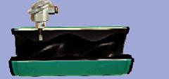
Improvements
in Suction Housings:
|
Features |
Benefits |
|
Oversized
Open Hopper Inlets |
Handle
thicker liquids |
|
Special
Compression Zones |
Increased
volumetric efficiency |
|
Oversized
Hopper With Double |
Eliminates
bridging Handles
filter cake up to 55% solids |
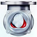
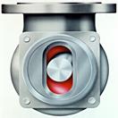
Improvements
in Pumping Element:
|
Features |
Benefits |
|
New
2 x 3 rotor/stator geometry |
Increased
flow per revolution and reduces initial pump cost. |
|
Equal
Wall Stators |
Doubles
pressure capability per stage |
|
Tie
Rod Construction |
Easy
stator change out with standard socket set |
|
Hollow
Cast Rotors |
Increase
rotor and stator service life |
|
Temperature
Probe |
Protects
against dry run |
|
Ductile
Coated Chrome Rotors |
Extend
wear life of rotor Does
not flake off like standard chrome coatings |
Let us know if you may have any questions. We would be glad to help. E-Mail your questions to: