Article 20:
WHAT HAPPENS WHEN A PUMP NO LONGER
OPERATES AT OPTIMUM CONDITIONS (Part 2)
In June of 2003, we started to discuss hydraulic implications of
pumps operating to the left of the best efficiency point (BEP). Low efficiency,
high radial loads, noise, vibration - become a real problem when that happens.
Damage to the seal, shaft, couplings and poor reliability are a real and direct
result of such operation. However, is it possible to quantify “Reliability”? What is
the impact on the equipment Life Cycle Cost, when a pump operates, say, 40%
off-peak? How much does this cost the plant? – not just in energy alone (that
aspect we covered in June), but – in terms of … seal replacement … bearing life
… coupling repairs … cavitation and recirculation damage cost … and so on. Is
it possible to derive at some factors which would relate the maintenance
dollars spent – to the inefficiency of the pump operation?!
In Part 1 (Article 19), we talked about the
effects of pumps operating at off-peak flow on efficiency and did an estimate of the wasted energy. That
discussion now has been published as so please feel free to examine it there.
This month, we are now examining the effect of such off-peak operation on
radial load, cavitation damage, and other aspects – and linking these to the
estimate of the actual plant costs. To do that, some assumptions had to me
made, and we would like to hear from you if you agree, or disagree, with these
assumption. As times goes on, this fledgling theory of operation-to-reliability
costing method may develop into a more comprehensive method, and the input from
the users will help make the next step.
In the recent years, the importance
of improving the overall reliability and plants uptime resulted in renewed
attention to the reliability assessment of the individual system components.
Pumps constitute one of the major classes of the plant components, and directly
contribute to the overall economics of the life cycle evaluation.
Let’s take a look, for example, at the advantages of the use new materials,
such as structural composites, with regard to parts upgrade program (pump
impellers, wear rings and bushings), as well as complete pumps. The reliability
and savings can be achieved with focus on the following:
Significantly reduced weight (80% lighter then metal) with
excellent tensile strength, approaching metals
Superior chemical resistance for most demanding tough chemicals
Abrasion resistance – up to 15% solids
Dry-running – continuous 3-D interwoven woven graphite fibers
providing good self-lubricating properties
Cavitation resistance exceeding bronze and stainless steel
Improved rotordynamics, longer seal life and bearing life
extension
Quality: these thermoset parts 5-axis machined from solid block
(no unbalance), as compared to injection-molded or cast thermoplastics (voids
and crevices result in unbalance)
Higher efficiencies due to tighter clearances allowed and superior
finish
Let’s also compare open versus
closed impellers. Open impellers have traditionally been accepted as a standard
design configuration of the ANSI pumps for chemicals. Initiated as far back as
1961 (originally called an AVS Standard), ANSI pumps have been installed in
numerous plants, and established a convenient and accepted standard to which
both manufacturers, and the end users, could readily comply. ANSI pumps, made
by different pump manufacturers would adapt to the same piping and baseplate
dimensions, thus making them dimensionally interchangeable, although the
internal parts geometry differs from one manufacturer to another.
The main advantage of the open
impeller design is cost. They are easier to cast and clean up at the foundry,
especially in case of sand casting process, which is often applied to iron
construction. Stainless steel designs are typically made using precision
patterns, and cleanup of passages from the mold residue is less of an issue,
but still a less expensive operation.
With the advent of the mag-drive
designs, however, closed impellers became a necessity, mainly due to a need to
reduce the axial thrust. Carbon or silicon carbide thrust washers, lubricated
by the products, do not have the same load capability as antifriction ball
bearings. Thus, a need to reduce the loads necessitated the change toward the
closed impeller designs.
However, substantial reliability
benefits can be achieved by replacing open impellers by closed impellers, -
even for the standard designs that utilize single or double seals, or packings.
Although the benefits of this approach have always been understood, the
quantifiable justification has become possible only recently, as new
reliability methods and approaches became available, using a Life Cycle Cost
Method (LCM).
Benefits
The benefits of the closed impellers
are materialized in (4) following areas:
Bearings Life
Seals Life
Efficiency improvement
NPSH
1) Bearings
As a typical example, consider a typical
MTX frame ANSI end suction overhung open impeller pump. Typical radial load FR
= 400 lbs and axial load is FA = 900 lbs. The equivalent dynamic
load is calculated as:
P = XFR + YFA
= 0.63 x 400 + 1.24 x 900 = 1368 lbs
This load is carried by the 5306A
double row ball bearing, which has a dynamic load coefficient C = 16,400 lbs,
which results in L10 life calculation as:
L10 = (C/P)3 x
106/(60xRPM), and adjusted by the a23 coefficient,
reflecting oil optimization (typically a23 = 2.5)
Thus, Lna = 2.5 x
(16,400/1368)3 x 106/(60x3600) = 20,052 hrs, i.e. 2.3
years.
ANSI spec requires 17,500 hrs
bearings life, which is approximately in agreement with calculations.
However, the axial load (FA)
used in these calculations, can change dramatically, depending on the position
of the impeller within the volute, the height of the pump-out vanes (POV), and
the gap between the pump-out vanes and the casing wall. The design value, used
at above calculations, is at the assumed design value of 0.060” gap between the
POV and the wall. The main reason
to use pump-out vanes (POV) is to change the pump axial hydraulic thrust:
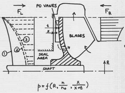
The
rotation of the impeller results in “dragging into rotation” of the fluid in the
gap between the impeller and casing walls. This is similar to a motion of a
teaspoon in a cup, or a disk spinning inside containment. The resulting motion
is referred to as “forced vortex”. Such vortex sets-in in the front and back
gaps – between the casing walls and the impeller front (shown on the right) and
a back hub (shown on the left). The pressure distribution in the gap is
parabolic – higher at the impeller OD, and gradually reducing towards the shaft
centerline.
Pressure
time area is force – which is exerted on the impeller from both sides (FR
and FL). The difference between these forces is hydraulic axial
thrust, which is ultimately transmitted to the bearings, and thus is desirable
to be small. This pressure at a given position in a gap depends on the radius,
rotational speed of the fluid (divided by the impeller rotational speed), and
the gap.
Curve
(1) shows the static pressure distribution behind the impeller hub without the
pump-out vanes. As we know from basic hydraulics, - the faster the fluid moves,
the lower the static pressure is. So, if we could make the fluid in the gap to
rotate faster, the static pressure would be reduced, and the force FL
to become smaller – closer, and hopeful equal to the FR – to reduce,
or eliminate the net thrust.
Without
the POV, the fluid in the gap is rotated only by the friction (drag) of the
impeller hub wall. It rotates with the same speed as the impeller right at the
impeller wall surface, but (so called “no-slip-condition”) is not rotating at
the casing wall, since that wall is stationary. Thus, on the average, the bulk
of the fluid in the gap is spinning at the angular velocity equal to half
of the angular velocity of the impeller.
But,
if we add the POV, the fluid becomes “trapped” within the POV space, and thus
rotates with the same speed as the impeller – i.e. double of what the fluid
does in the absence of the POV. This, of course, assuming the gap between the
POV and the casing wall is (theoretically) zero (x=0). The number of the POVs
actually does not have to be equal to the number of the impeller main blades,
but often is, due to casting production process, for simplicity.
Obviously,
the gap “x” can not be zero, so the actual reduction of the pressure profile
(curve marked as “2”, is less, depending on the gap “x”. And, if this gap
becomes too large, the effect of the POV diminishes, and eventually disappears.
It turns out that, the POV are most effective at x=0, and become completely
non-effective when x=t, i.e. when the liquid gap (x) becomes
equal to the height of the pump-out vanes (t). (Papers are
written on this subject, such as a well known Zanker’s paper), explaining whys
and whats, and those of you who have a couple of sleepless nights to study them
– let us know, and we will get you the material).
The
balancing holes are also used to reduce pressure distribution, i.e. a similar
idea as the pump-out vanes. In fact, this is why they are called “balancing”.
To be effective, the impeller must have a tight clearance between it and a
casing (not shown on a picture above), to separate the higher pressure zone,
from a lower pressure zone. The balancing holes thus connect the back of the
impeller with the inlet area, where pressure is low (close to suction). Some
leakage will occur, reducing the efficiency. If there is no clearance, such as
shown above, the leakage will be greater, reducing the efficiency even more.
Another
reason for the POV is to reduce the pressure at the mechanical seal area. The
effect of these vanes can be very strong, and, sometimes even result in
creating vacuum, and boiling out of the liquid. This could be trouble, as
mechanical seals do not like to operate in a vapor environment.
Regarding
the performance – there is price to pay for the thrust balance, as the
additional power required to spin the liquid faster takes away the efficiency.
This is why, the higher energy pumps, such as API, or boiler feed, rarely have
the pump-out vanes, while the ANSI pumps, which are relatively lower horsepower
units, have these.
Note
the picture above shows an open impeller. The front gap, between
the impeller and the casing, must be tight (typically 0.005 – 0.015”, depending
on a pump size). The challenge is thus to maintain both front and back gaps
small – from the efficiency and thrust standpoint. Closed
impellers solve this problem, but at the expense of reduced ability to handle
stringy, such as fibrous, solids.
Regarding
the “reverse vane” impeller. The impeller shown above is a standard design, such
as, for example, manufactured by Goulds, model 3196. To adjust the front
clearance, the rotor must be pushed against the casing, and then backed-off by
the amount of design clearance. It is sometimes desirable to keep the casing
piped-up, as it is somewhat a chore to re-pipe it. This requires re-setting of
the front gap, during maintenance, on site – and, if it rains or snows – you
freeze and catch a cold!
If
the impeller is “turned around”, such that the clearance gap is between the
impeller and the stuffing box (or a sealing chamber), then this clearance can
be set at the shop, and the rotor can then be simply brought to a casing and
bolted on quickly. Example of such design is former Durco
Clearly,
the perceived advantage, widely publicized in the past by the manufacturers, of
the ability to adjust the impeller front clearance to compensate for wear is
quickly, can do more harm then good: as impeller is adjusted forward to close
the worn out gap, the back clearance increases – by the same amount. The
increased gap between the POV and the casing wall can effect pressure
distribution dramatically. The resultant axial thrust can actually triple, i.e.
FA = 3 x 900 = 2700 lbs
Additionally,
as impeller wears out, the removed metal causes radial unbalance, which adds to
a hydraulic thrust. Estimates vary, but 50% increase in radial load is quite
possible, so that FR = 1.5 x 400 = 600 lbs
The
equivalent dynamic load then becomes: P = 0.63 x 600 + 1.24 x 2700 = 3736 lbs, which
impacts bearings life dramatically:
Lna = 2.5 x (16,400 / 3736)3 x 10⁶/(60x3600)
= 979 hrs = 1.3 months !
2)
Seals
The
impeller wear, and the resulted unbalance, results in increased radial load and
shaft deflection:
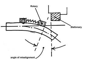
Seal
manufacturers have done research which shows exponential deterioration of seal
life, including leakage and failures, when the angular misalignment exceeds
0.002”. At 50% increased radial load, a normal projected seal life of 2 years
can be reduced to less then 6 months.
The
problem can in fact become worse if the impeller is adjusted (as was discussed
above) axially due to wear, because this results in reduced seal spring
tension, lowering closing force and initiating premature leak.
3)
Efficiency
Theoretically,
an open impeller with negligible front clearance is somewhat more efficient
then a closed impeller. However, efficiency drops very quickly as actual front
clearance is increased due to wear. When initial 0.005” front clearance is
opened up to 0.010”, a pump can loose 10% efficiency due to increased leakage,
and at 0.015” there would be approximately another 10% efficiency reduction.
Obviously, none of this is an issue for closed impellers.
4)
NPSH
The
impact on NPSHR is similar to the efficiency. The increased front leakage
effects the NPSHR and could add another 2-4 feet when clearance doubles. The
R-ratio (NPSHA/NPSHR) varies form one installation to another, but a typical
rule is to have at least 5 feet NPSHA above the NPSHA required. When almost
half of this margin is taken away to front leakage, the R-ratio can become too
close to the NPSHR and the cavitation bubbles that begin to form even before
the NPSHA reaches the value of performance loss, become active enough to cause
caviation damage:
It
is difficult to quantify the decrease in impeller useful life due to worsen
cavitation condition, since there is no known statistics published on the
average life of the impeller as function of NPSHA, and some reasonable
assumptions may be required. If we assume that a non-cavitation impeller could
last 10 years until replacement, the reduction of the NPSHA margin from 5 feet
to 2.5 feet would affect the life in direct proportion, i.e. reducing it to 5
years. More studies, however, would be required to quantify this particular
effect on reliability.
LIFE
CYCLE APPROACH
In
order to compare different designs using Reliability methods, a Cycle Basis
needs to be established, which is also applied to other types of components. A reasonable
basis for comparison is a 5 year interval. Another assumption is made that,
during this time cycle, a pump operates in several descretised steps of
operation, for example 20% in regime 1, another 20% in regime 2, and so on.
This allows a more uniform distribution of various regimes of operation
throughout the cycle and a better averaged comparison. We will apply this
method to each of the selected elements that are affected by the forcing
function, such as:
a)
Bearings – life decreasing from 2.3 years to 1.3 (0.21 years) months within
five zones for the purpose of averaging:

The
above distribution can be a safe assumption when a continuous statistical data
is limited. Otherwise, if the load is known at each interval, and the bearing
life can be calculated at each of the intervals, the averaging can be done by
summing the life at the intervals and dividing by the total time span (5 years
in case if Cycle Basis is selected as 5 years).
For
linear distribution, the averaged weighted life would be:
(2.3
+ 1.75 + 1.2 + 0.65 + 0.1) / 5 = 1.2 years
b)
Seals – using similar linear function (2 years life at interval 1, reducing
linearly to a calculated 0.6 years life at interval 5), we get:
(2
+ 1.62 + 1.25 + 0.88 + 0.5) / 5 = 1.1 years
c)
Efficiency - assuming pump efficiency
drops from 70% to 58% (70, 65, 60, 55, 50), we get the weighted average:
(70+65+60+55+50)
/ 5 = 60%
To
relate this to the life cycle factor, we need to evaluate the energy savings
due to efficiency difference. Assuming a pump with a 10 hp motor, running 100%,
at $0.06 per kWxhr, this results in:
10
x 0.746 x 24 x 365 x 0.06 x 0.70 = $2755
10
x 0.746 x 24 x 365 x 0.06 x 0.60 = $2352
Annual
energy savings $402 per pump, which is roughly a 1 year payback period basis a typical
cost of a replacement impeller.
d)
NPSH margin – assume reducing from 5 feet margin to 2.5 feet (5, 4.4, 3.8, 3.1,
2.5), we get the averaged cycle value of:
(5+4.4+3.8+3.1+2.5)/5
= 3.8 feet
If a
10 year life is assumed with a full specified margin (5 feet), then the reduced
life is 3.8/5 x 10 = 7.6 years
Note:
the actual life of impellers also varies depending on applications and pump
types. Double suction cooling water pumps, for example, are notorious for
NPSH-related problems (Ref. [10]).
COMPARISION
Open Closed
Bearings
life factor 1.2 yr 2.3 yr
Seals
life factor 1.1
yr 2 yr
Efficiency
factor 0 yr 1 yr
NPSH life factor 7.6
yr 10 yr
Total: 9.9
yr 15.3 yr (54% improvement)
MTBF
Having
established life factor comparison, the next step is relate these to the Mean
Time between Failures (MTBF), which is typically known relatively accurately
for a given plant. Assume for example, a plant averages 3 years MTBF. The 54%
improvement, calculated above, would increase the MTBF to 3 x 1.54 = 4.6 years.
What
does an improvement in 1.6 years, per pump, in MTBF mean to a typical plant?
1.6
added years is equivalent to an improvement of 1/1.6 = 0.62 failures pre year.
The cost of equipment failures is a total of individual components: parts,
labor and lost production. While replacing of impellers, seals, bearings, and
other parts is costly, a cost of lost production can even more significant. For
a typical chemical plant with thousands of pumps, this could be a very
significant number. The cost of a lost production also varies from one plant to
another, and literature has values anywhere from $5,000 per hour to $200,000
per hour. At a $10,000 per hour value of lost production, each pump would
result in 10,000 x 0.62 = $6,200 difference, and, with a population of 1000
pumps at a plant, this amounts to 1000x6200 = $6.2M for a plant!
Clearly,
these vary from one plant to another, but the importance of the issue is
clearly there, and it can not be ignored.

Example
above: metal impeller, reduced life due to corrosion attack. Composite
(continuous graphite fibers in epoxy matrix), not affected by chemical attack.
Also,
an ANSI pump, installed at the chemical plant, resulted in extended life due to
lowered weight, as well as improved chemical resistance. These cases are
currently being prepared, and will be included with the final manuscript.
A
retrofit program of converting open impellers to closed impeller design present
substantial, real and immediate benefits to the end user. For a typical
chemical plant, or similar operating facility, this could be thousands, or even
millions of dollars, saved in maintenance, repair and production budgets. The
conversion process is straightforward and technically sound. The best approach
is to establish a planned program of replacing, starting from the worst
operating units and continuing to the next level, driving the plant reliability
record continuously upward.
New
technologies, such as engineered structural composites, present a timely and
effective opportunity to achieve maximum benefits and quickly. The combined
benefits of significantly reduced weight, substantial improvements in chemical
resistance, excellent abrasion characteristics, and superior cavitation
resistance, makes Simsite a material of choice for such program.
We
welcome your input on this topic, and will be glad to post your comments and
opinions at the Pump Magazine On-Line commentary board.
Dr. Lev Nelik, P.E., Apics
Pumping Machinery, LLC
August, 2003