PUMP
MAGAZINE: Questions
and Answers (111 - 120)
Question #111:
James, - do you have any vibration guidelines for Progressive Cavity
pumps? Our pumps are used in the water treatment plant setting to
transfer lime sludge.
Laith Hintz
Design Engineer
Advanced Engineering and Environmental Services, Inc.
Bismarck, ND
Laith,
Although we have done considerable analysis on machinery at water treatment
plants through the years, we do not have any specific vibration guidelines for
Progressive Cavity pumps. We have evaluated a large array of pumps at both
water treatment and wastewater management facilities.
I am not familiar with where you might find such guidelines, but I can refer
you to someone who has considerable expertise with a wide cross section of pump
designs. His name is
James E. Berry, P.E.
President
Technical Associates of
Dr. Nelik comments:
Laith,
- I am not familiar with vibration guidelines specifically for
progressing cavity pumps. There is a lot published and available on centrifugal
pumps, including single stage, multistage, vertical, etc. From the rotary
types, very little is published, both in open literature, as well as even via
internal guidelines by the manufacturers. The names of some of the leading PC
pump manufacturers are noted in your email, and, of course, there are others.
Neither Hydraulic Institute, nor API, publish vibration guidelines for PC
pumps, although they do cover centrifugal types very well.
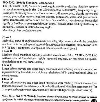
In the absence of such data, the best
advice I can provide is probably the same as implied by James, which they use
extensively in their work as he noted. Such general guidelines are defined by
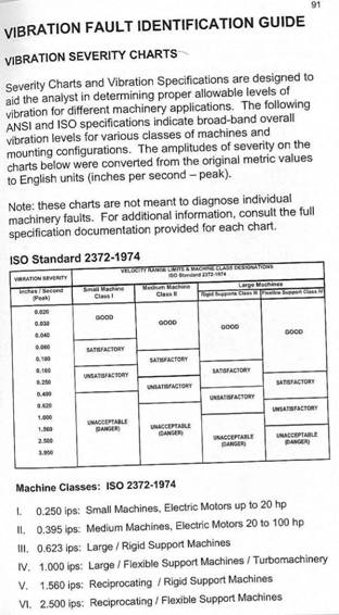
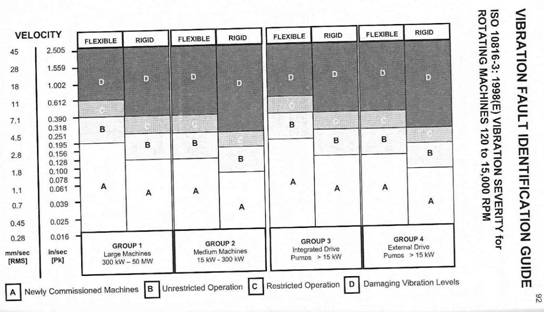
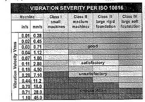
various ISO spec, such as ISO 2372-1974, ISO 10816-3, ISO 2372-1974, and some
others. Below is an example of one:
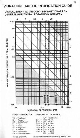
Keep in mind that two things effect
vibrations in PC pumps, in the opposite ways: first, they are inheritably
unbalanced, due to a so called “nutational” motion of
the eccentric rotor in relation to a stator – such motion of the eccentric mass
produces undesirable force; but secondly (fortunately) - they generally run at
low speed, typically below 300-400 rpm. I have found that when a PC pump
operates above approximately 400-500 rpm, vibration becomes a concern and
readily “feelable”. It depends, of course, also on a
pump size, length, number of stages, energy level, conditions of the support
(which is very important for a PC pump, or for any
other type for that matter), etc. - but 500 rpm seems to work well for me, as a
rough guideline.
I must say that, generally,
vibration-based troubleshooting is rarely done for PC pumps, although it is a
vastly acceptable, known and important way of troubleshooting root causes of
other pump types, especially centrifugal. Troubleshooting of PC pumps is
typically more pragmatic and rudimental. One of the reasons is perhaps that
there is relatively fewer PC pumps in the filed, as
compared to a much wider population of centrifugal pumps. Vibration analysis of
centrifugal pumps can help reveal and detect early issues with bearings headed
to failure, unbalance, misalignment, blade pass, and numerous other issues. The
issues with PC pumps tend to be less involved (less sophisticated perhaps a
somewhat bolder statement), as far as application of methods of detection of
internal faults, and thus vibration analysis did not enter the arena of PC
world as wide as it did centrifugals. PC failures are more likely to be caused
by dry running, stator chunk-out, overpressure due to bad (or sometimes
absent!) relief valve, wear, and shear-off of the joint, etc. Rarely, the repeated
cause of a failures, for PC pumps, are bearings, because other issues, as
noted, usually show up first - while, again, it is a very common issue with
centrifugals.
I hope this helps a little, and sheds
some light on at least reasons why this subject is relatively obscure, although
it still leaves your question open. It is an interesting subject, and I am
forwarding it to the Editor of Pumps & Systems magazine Mike Riley, to
consider publishing, as a discussion, and to ask our reader to comment,
hopefully uncovering more additional sources, standards or published
recommendations, as well as personal insights. In my own opinion, as a rule of
thumb, given a lack of a specific guideline, I would use a 50% higher limit on
PC pumps vibration acceptance level, as compared to centrifugal pumps. For
example, if a centrifugal pump, based on its standard, results in, say, 0.2 in/sec
velocity limit, I would use a 0.3 in/sec limit on a PC pump of similar horsepowers, and limit speeds to under 500 RPM. PC pumps
would run rarely at speeds above 500 rpm, although they do occasionally, and I
would then treat vibration limit on those as a special case. Even more
importantly, and perhaps more useful, would be not the absolute level of
vibrations, but trending. If a PC pump vibrates at 0.4 in/sec (a number
generally considered too high for centrifugals), but pumps well and have been
working fine for many years, taking periodic (overall vibration) trends may be
all you need. When such trend begin to show signs of increase, it could be an
indication of a problem beginning to develop. To avoid catastrophic failure, it
might then be a good idea to schedule an overhaul or a repair. But if failures
are frequent, you would likely find simpler explanation, even without a
vibration analysis. For example, excessive wear may indicate incorrect (too
tight interference between the rotor and stator. Too frequent “flaking” of the
rotor may point out on improper coated rotor. Rubber chunk-out may be caused by
dry running. These reasons are typically listed in troubleshooting guidelines
by the manufacturers, and if these guidelines are followed, plus common sense,
much trouble with PC pumps in field can be avoided.
Best
regards,
Lev Nelik,
Ph.D., P.E., APICS
President /
Technical Director
Pumping
Machinery, LLC
Note from the original
question by Laith Hintz:
Thank you for the
additional insight on PC pumps. My original question on vibration
guidelines for PC pumps stemmed from a general pump specification for a project
that required vibration analysis for all pumps covered in that section (mainly
centrifugal). From your discussion, it sounds like requiring
vibration analysis on PC pumps after installation may be useful but has not
become common practice. Thank you again for taking the time to
answer my question.
Laith
Additional input from Todd Brown, Moyno
Progressing Cavity Pumps company:
Moyno does not have any published guidelines
with respect to vibration values for our Progressive Cavity pumps. Because
of its inherent eccentric nature, the pump has natural movement, specifically
as you near the suction housing and stator. This situation coupled with
the vast array of mounting arrangements, platforms and foundations, makes it
very difficult to come up with a standard. I know of no standard in the
industry for Progressing Cavity pumps with respect to vibrations. When
asked, Moyno will perform vibration analysis on
specific units on the bearing (pump, gearbox and motor) locations only. I
know of no instances where we have failed to meet this assuming the entire unit
was rigidly mounted (i.e. not overhung).
Todd Brown
Moyno Pumps
Question #112: Hello,
I am in
Thanks, - if you can help me out or direct
me to information about cold weather pumping.
Regards,
Canada Water, Inc.
Pump Magazine responds: we are forwarding John’s question to our readers,
particularly to attention of those at pipelines and terminals. We would
appreciate if you could take a moment offering your opinion and ideas, and perhaps
share your methods of protecting pipelines from freezing in similar situations.
Let us know. Your
input is appreciated in advance.
Lev Nelik
Editor, Pump
Magazine On-Line
Blair Northen, Kinder Morgan
Pipelines, Atlanta, Georgia comments:
We transport mainly
petroleum products and don't normally have any water. I would suggest keeping
the water flowing where possible and using insulation / burial of
lines and heat strips on equipment that sees static conditions.
Otherwise - drain the water
out!?
My climate here typically
does not experience temperatures below 0 deg. F and not for extended periods.
I can
not give you an actual flow rate that will work but for the most part if
the water is moving it is above the freezing temperature. Any
insulation (soil, hay, foam, even snow in really cold temps) will help keep it
above freezing. Typically heat trace is not practical. We have many
instances where non insulated pipes are exposed directly to cold temps
(particularly bridge crossings) and freezing has not been an issue for
us. A neighboring water utility has installed a small blow off on a pipe
hanging from a bridge crossing a stream. This “leak” occurs all winter
and I am not aware of any freezing issues. In some older cities in
Europe,
In my water treatment
plant, things are different. The water flows by gravity and flows very
slowly. Where I have valves in open outdoor tanks, I need to keep the
valves submerged under water all winter. I learned the hard way what it
takes to thaw out a 48 inch butterfly valve that is frozen closed with water
behind it. Keeping the valves submerged reduces the useable capacity but
it is necessary to have any use of the tank. For my indoor filter
operations, the valves are wrapped with heat trace for the winter, it is
inefficient and expensive but it works. Once the tanks have frozen over,
we need to keep the ice from pulling on the wires for the pumps; this is
typically done with sledge hammers and manual labor. I wanted to try a home made bubble system this winter but did not get around
to it (maybe next year). We also lower the water level under the ice
because sagging ice is not nearly as destructive as heaving ice.
If you have any others
questions or experiences you want to share, give me a call. If nothing
else we can complain about the water operators in
Readers Feedback:
Thanks for getting me contacted with your
network. Just for your info, we have been successfully running three Godwin
pumps continuously as the inflow varies. The temperature was – (minus!) 42 with
a 20 Km/hr breeze for a few days on site. It took some effort to combat
freezing of the 1000M 12” steel pipeline. If anyone else ever asks about cold
weather pumping, feel free to send them to me. At
www.canadiandewatering.com
there is a lot of experience and expertise of fluid handling in extreme
conditions.
Regards,
John Carlsen
Question #112: Good day Dr.
Let me introduce briefly. I'm a sales guy working out of
As you may know we are fire fighting pumps manufacturers, and lately we are
working on a project for fire pumps (diesel driven) that are required to be
compliant to API 610. I'm not sure on the content of the norm but I was told
that is applying to the process/chemical/petrolchemical
pumps only.
Do you have any comment on why a fire pump should be API 610 compliant?
Looking forward to read from you.
Thanking you in advance for the time you'll be dedicating.
Best Regards,
Ing. Benvenuti Andrea
Peerless Pump Company
Torino -
Dr.
Mr. Andrea, - as you know,
fire pumps are typically split case or vertical turbine pump types, although
other types are applied occasionally as well. They do not fall under a category
of API-610, although are governed by a fire pumps spec, which is more stringent
as compared to a similar pump not intended for fire duty. API-610 design is
very tough and stringent, and applies, as names implies, to petroleum industry,
such as refineries and other petroleum operations. Some other industries,
however, have adopted API-610, to either complete, or partial, intent,
recognizing the fact that pumps designed to API-610 specification are much more
robust and reliable for tough applications. Example would be power generation
industry, which invokes API-610, at least partially, for the boiler feed pumps
– hot, high speed, demanding machine, with utmost priority to reliability.
API-610 covers a variety of technical issues, such as shaft deflections, nozzle
loads, etc. etc., and thus not every pump manufacturer can comply.
But what sometimes happens is this. A typical refinery consists of two types of
equipment – battery limits (where oil is actually being refined), and
supporting equipment. A pump in the basement of the cafeteria, for example,
supplying HVAC needs there, may never see situations as tough and critical as
its brethren a mile away, in the battery limit area. But, a purchasing
department may require a supplier to comply with the API spec, because the
pumps are technically slated to the refinery. Fire pumps may come under similar
considerations.
Thus, each application needs to be reviewed on its merit.
I am copying your note to Peerless folks in
I hope this helps. Feel free if any questions. I might be in
Regards,
Lev
President / Technical Director
Pumping Machinery, LLC
Andrew Warrington, Vice
President of Sales, Peerless Pump Company, comments:
Andrea - Well I am honored to be considered to
"look Italian" by Dr
We often meet this problem. In fact of course, API and NFPA rules are often
even contradictory in many ways (e.g. materials where NFPA or at least UL or FM
dictate a cast iron case and bronze impeller where most API specs would call
for at least cast steel I would think). So it's a non sequitur to say I would
like an FM/ UL approve API fire pump. Many try and we do include some of the
API style requirements in our fire pumps but we (and I don't think anyone else)
has ever made a fully compliant API UL/ FM listed fire pump.
When I was with SIHI for example we supplied many of their specialty pumps to
refineries where the traditional API guys made the centrifugal pumps and for
some reason they wanted a vacuum pump or a side channel pump or a fuel transfer
pump. We would always fight the exception battle and supply something that was
perfectly good for the application but did not fully comply with API (which by
the way changes like the wind with all the new editions anyway). Usually we
could win the battle but the oil companies were always reluctant as they were
so used to getting API pumps.
Another example is when I was with SIHI again we sold ISO standard
Now in Peerless we meet it all the time and the solution is to ask why they
need this or that feature. Our fire pumps built to our standard design are the
best in the business at doing what they do - putting fires out. They are pretty
much a time tested good design for that. They don't do too well supplying
cracking reactors or pumping hot crude or finished petroleum fractions. Then
again, that's someone else's business.
Anyway, I am off to put on my Armani suit and go out on the town.
Ciao,
Andrew Warrington
Vice President of Sales, Peerless Pump Company,
Tel
www.peerlesspump.com
It looks like Andrea got
the help he was looking for, as he notes:
Thank you for your explanations and will certainly be happy to
take you to one of our best restaurants!!
Best Regards,
Ing. Benvenuti
Andrea
Question #113: Dear Dr. Pump,
It is being told that the vibration levels
specified in the 9th Edition ( V(filtered)
= 0.67 X V(unfiltered) ) is by error and 11th edition is in the
process of correcting the mistake. Is it so? Please elaborate.
K.Chakravarthi
Engineer, Export Services.
Kuwait Oil Company
Answer:
Regarding the vibration levels being "wrong"
or different in API 610, 9th edition than they will be in the next edition,
here is the logic:
As published in the 9th edition: vf < 0.67 vu, for
discrete frequencies
To be published in the 11th edition: vf < 2.0 mm/s RMS or 0.08 in/s RMS
Obviously 2.0 mm/s and 0.08 in/s are 0.67 x the
overall values of 3.0 mm/s and 0.12 in/s, so there is no change in the values
between what is now published in the 9th edition and what WILL be published in
the 11th edition. However, there is a significant difference when one
misinterprets what was meant by the simple vf <
0.67 vu.
What has happened through some reported
misinterpretations is this: the purchaser of equipment interpreted API 610 as
meaning that the filtered vibration should be 0.67 x whatever actual overall
vibration level was measured. This meant that, with a very well
manufactured pump that exhibited a very low overall vibration level,
it could never pass the filtered values of 0.67 x the low measured overall
level. This was not the intention of API 610. The intention is that
the LIMIT for filtered vibration would be 0.67 x the limit for overall
vibration. The table in API 610 is a table of limits. Because of
the misinterpretation discovered, it was decided to revert to actual numbers
for filtered vibration limits in the next edition.
This, by the way, is NOT the case for shaft displacement measurements and those
figures have not been changed from the 9th edition.
By the way: the vibration limits published in API 610
are meant for performance testing in the vendor's shop, but they happen to work
quite well as field vibration limits as well.
In addition to the above, I rarely
rely on exact value as specified by spec, as in my experience the field
situation differs considerable from theoretical. Filtered, unfiltered overall, rms, peak-to-peak, zero-to-peak, etc. can be very confusing
to most folks at the plants, who do not use vibrations as the sole way of
making a living. Normally, these days, reliability engineers are the same ones
responsible for machinery reliability, mechanical, structural, vibrations,
hydraulics, and other issues. Years ago, these topics used to be sliced around
more people, but today, with plant’ personnel reduction, much fewer people
carry more burden. Perhaps partly as a result of that, a more pragmatic (some
exceptions are noted further below) field approach is to read vibrations by
magnetic pick up probes (accelerometers) and convert the signal automatically
by the instrument into velocity (RMS) values. While there should,
theoretically, be differences on the allowables,
depending on energy level, speed, etc., some general guidelines, in my view,
are sufficient, and perhaps are as:
- A. under 0.10 in/sec – fully acceptable
- B. between 0.10 and 0.25 in/sec – normal
- C. between 0.25 – 0.30 in/sec – cause of concern
and more detailed analysis, but not a shut down
- D. over 0.30 in/sec to 0.40 in/sec – to be
considered as corrected during upcoming outage
- E. over 0.40 in/sec – potential failure could be
imminent
Or, for a more formal guidance you
can refer to ISO specification:
These are overall. Individual
harmonics (FFT) should be analyzed only when troubleshooting, such as over case
(C), but below it I would not waste time. Only in such cases, a more involved
study is invoked, and typically done by vibration specialists. At that time,
preferences between velocity or acceleration, amplitude, time domain versus
frequency domain, begin to emerge, etc., - but all within the realm of
relatively rare, albeit important, group of situations. Perhaps 95% of field
troubles do not invoke that level of detail, and, while remaining extremely
interesting and fascinating, remains under the umbrella of somewhat academic
mould.
Many critical machinery units have
installed proximity probes, which read amplitudes, rather then
velocity, picked up at the journals of the rotating shafts. These have more
elaborate approach, taking into account electric run-out, etc., and fed into
automatic plant system, which could trigger machinery shut-down in case of a
problem, when vibration accedes a set value. Examples
of such would be boiler feed pumps, and, true to your question, pumps at the
refineries, for which, in fact, the API-610 spec was written originally for.
But even for those, a debate over the exact value of the set points could
questioned as important, as most practitioners are aware of what constitutes
high, moderate, or low vibration.
As time changes, more elaborate
schemes come out, but many of these are products of people continue painting
the same painting over, never satisfied with what already exists. In
vibrations, good data have been in existence for years, and charts, graphs and
calculations are published by Vibration Institute, and other practical
organizations. These reflect years of experience, and should be handled by
vibration professionals. I doubt that a pump vibration is any more or less
damaging to a pump in 1950 as it would be in 2007, and constant change of the
acceptance criteria is, in my view, is a waste of time.
However, your question is a good one,
and I thank you for that, and copying a President of a local chapter of
Vibration Institute for in formation. John Visotsky
will be speaking on the subject of vibration at the upcoming PumpTec-2007
Conference in
Lev
President / Technical Director
Pumping Machinery, LLC
Question #114:
My application is for a typical sanitary
sewer lift station and force main design for small to mid size collection
systems, say 6-inch to 16-inch force mains.
Quite often, our parameters require that the
design pumps over a
The question is: what is the latest trend
for the best (and safest-raw sewer) mechanism to use to break the vacuum at the
Russ Brink, P.E.
Engineering
Management Incorporated
Lawrenceville, GA
We
have asked Chris Staud, a Senior Engineer with a City of
Russ:
The City of
City personal retire and don't pass along where
some of these pits are, or developers develop the land and change the entire
look of what use to be a field, or your maintenance road disappears due to lack
of use. Or, my personal favorite occurs when a developer buries your pit under
several feet of fill. It is a challenge to find these manholes with their
air-release valves especially if you don't know if you have the as-built
drawings. Opening the pits sometime
create some interesting problems when you discover that a den of snakes have
taken up residence in your air-vacuum release pit. Our people learn to move
fast when confronted with a den of snakes.
I personally prefer
Hope this helps.
Sincerely
Chris Staud, PE
City of
Question #115:
Dear Pump Magazine,
I have a question regarding the specific gravity limitation of a
pumping fluid: Liquefied Petroleum Gas (LPG) - primarily mixture of propane and
butane which is received from refinery FCC (Fluidized catalytic Cracker) unit.
We have two-stage pumping:
1st stage:
Pump is a vertical centrifugal. Fluid is received in suction piping
directly from LPG sphere. However, the impellers of the 3 stage pump are at 20
feet below from ground level in a canned structure to create the required
NPSHA.
Suction Pressure in the piping: 50 PSIG (before entering the
underground can)
Discharge pressure: 284 PSI
Rated Flow: 950 GPM
2nd stage:
Pump is horizontal centrifugal pump. It receives same 950 gpm from discharge of the first stage(above)
and discharges to underground cross country pipeline. We normally pump LPG in the
specific gravity range of 0.535-0.545 at ambient 86 °F.
We recently got LPG from the refinery with specific gravity in the
range of 0.345-0.485 for 5-6 hours. We do not have alarm/tripping of pumps
right now on receiving low density of LPG. Hence, we felt the need to
incorporate tripping of pumps on receiving low density since this is an issue
having direct relation to the quality of product we are receiving from the
supplier. Such a qualitative change may not be acceptable to the customer to
whom we are supplying the LPG through cross country pipeline (1250 KM).
I would like to know if such a low density product is harmful for
the pump operation, especially for the first stage pumping since we are having
narrow NPSHA-NPSHR margin in first stage pumping. Also, if we receive low SG
LPG, it indicates that the propane quantity may be higher than normal (and
butane lower than normal) which results in higher vapor pressure since propane
has higher vapor pressure as compared to butane.
The pump O&M manual indicates the SG range as 0.515-0.585 but
does not write anything explicitly about possible problem in encountering low
sp.gr. fluid. Please advice at the earliest.
Yours truly,
Somak Gandhi
GAIL Ltd.,
Answer:
This is a multifaceted question. One involves low NPSH
margin, which usually (not always) is not a problem in practice with
hydrocarbons, because of the vapor-volume relationship. The second relates
specifically to low specific gravity and possible effects on the pumps. The
API standards have always suggested larger running clearances for specific
gravities below 0.7 because of loss of inherent lubricity and the consequent
danger of wear part damage. With good running material combinations, the
lower specific gravity should not be a problem, especially in the situation
described where the pumps were continuously running. As a safeguard in
these applications, it is beneficial to recommend superior running materials,
such as graphite products (Graphalloy as an example)
or other suitable nonmetals for stationary running parts (PEEK comes to mind as
another option). With this protection, specific gravity excursions are a
non-issue.
I have also discussed your question with engineers I
know at Colonial Pipeline company in US Georgia, from the viewpoint of the pump
operators. Pipelines move gasoline, oil
and other products thru their pipelines, and utilize high energy pumps,
including multistage pumps. Such pumps have long rotors, supported at the ends
by journal oil lubricated bearings, and a center bushing (obviously product
lubricated) to assist rotor support. Contact of the rotor to rings and bushings
is always an issue, especially for low lubricity fluids, where fluid film in
the clearances is weak and offers little support. Such ability to support the
rotor in clearances is often characterized by a so-called Lomakin
effect, i.e. ability of a bushing (or a wear ring) to develop sufficient fluid
film to provide dampening and stiffening forces supporting the rotor from
contacting stationary part. In such cases, occasional rotor to bushings contact
takes place, a known problem and a challenge for the pipeliners.
Self-lubricated materials, such as Grahpalloy, for
example, provide significant benefit as a solution, to prevent catastrophic
failures.
Lev
Pumping Machinery, LLC
Question #116:
Does anyone know what C factor should be
used for lay flat and rigid hose, or know where I can find that information? We are in the pump rental
business and we need to calculate head loss in order to select the right pump
for our customers. We have the option of using HDPE pipe, Quick Disconnect
steel pipe (Bauer), Aluminum Victaulic and hose (rigid suction hose and layflat). The rigid hose has either nitrile
or poly liner so the C factor is known. It’s the layflat
hose that is unknown. There are a lot of commercially available TDH programs
out there and I have researched many. I find them to be overly complicated for
our needs and too expensive, so I wrote my own program. It works fine for what
we need it for and the Hazen Williams formula is accurate enough for our
purposes. Going Darcy-Weisback increases the
complexity of the programming and I have neither the time, ability or need to
go that route. I was hoping that someone would have some idea, any idea of a
number that would work for layflat hose, 80, 100, 120, whatever. The key is that we don’t have to be dead-on
accurate for our type of business. If you can suggest a number I would be more
than happy to use it because I have had no luck to this point finding anything.
Pat Black
Engineering Manager
BakerCorp
562-342-7947
Answer:
Pat,
DFS FlowNet
by ABZ had a good database on hoses and tubing but does not use C Factors. Some
people found 0.000075 feet absolute roughness works good for calcs for new general purpose hose up to 4” in diameter. I
would probably use 0.0001 feet or even higher to be safe for new stuff and
higher if fouled by grit or slime. I asked some of my colleagues also,
and they did not find a value for a flat hose. Some other references do not
state a roughness for hose. What did a hose manufacturer say? Unfortunately,
some of them make good hoses, my often do not provide a roughness factor, but
it is worth a call. I believe that hose is similar to HDPE pipe; Nipak (a Driscopipe distributor in WV) recommended to use C=150 for
HDPE. Vinyl hose would be similar to Polyethylene pipe and C factor may come
close to reality on small pipes. Seelye
book lists the following on page 22-03:
For the Hazen-Williams Formula, for Fire Hose:
Extremely smooth: C= 143
Robber Lined: C= 125-140
Mill Hose: C= 100-120
Unlined Linen Hose C= 85-95
Please note that this info is taken from a book
that was published in 1960 (originally 1945).
Elwyn Seelye was a
Civil Engineer with over 35 years of experience when he edited this book. I do
not know if PVC hoses were available at that time and believe that PVC would
approach the C used by the HDPE manufacturers, C=150.
Are you evaluating an old
installation, or are you considering a brand new design? If an old one, I can
recommend some ways to assess the C-factor in a somewhat round-about, but
pragmatic, way. You could easily check these values by installing two pressure
gauges on a flat water-hose and just calculating the pressure loss this
way. You may need a “5 gallon bucket” to check the flow rates etc.
Regards,
Lev Nelik, Ph.D., P.E., APICS
President / Technical Director
Pumping Machinery, LLC
Question #117:
Dr. Pump,
Please advise the source of Asarcon-520 material.
Thanks,
Bill Bogdan
Crane Aerospace & Electronics
Our contributing affiliate, Luis Rizo
comments:
Hi Bill,
Asarcon 520
was a lead impregnated bronze used for sleeve bearing in horizontal split
pumps. I have not seen it in use, since my days at
Years later, while I worked for Exxon as
a Rotating equipment engineer we began using graphite impregnated carbon (Grapholloy) (www.graphalloy.com/html/products.html?gclid=CK2M_Iuco5UCFQSsGgodwkGSkQ) sleeve bearing for pumps and Thorlon
for the slower running centrifuges. We retrofitted some old packing pumps
in hot oil services to mechanical seals. These pumps, by design, depended on the packing for shaft support. In
order to support the shaft and allow the mechanical seal to live, I installed
steel encased Grapholloy encase in a steel sleeve
with spiral grooves between the bearing house and the old packing box.
This eliminated the run out and allowed for the seals to run true and not leak.
The Graphalloy material can be used in plain
stock or encased in a steel sleeve to add strength, depending on need.
In either case you
must calculate the loads to assure that the bearing is appropriately
designed and support the shaft loads and that it is not on a node in the
flexural curve.
I hope this helps,
Good Luck!
Luis F. Rizo, PE
GE
For additional information on similar
materials, also review www.pump-magazine.com/pump_magazine/q&a/faq1_20/faq1_20.htm
(question #15)
Question #118:
Dear sir,
I want to design the pumps handling LPG
(liquefied petroleum gas).
The tank outlet from the top, not from the
tank bottom.
My question is how to calculate the NPSHa
for LPG pumps. I have a closed vessel with 12 bar pressure. Vapor and liquid at
the vapor space are equalized. Liquid level is
above the pump suction centerline.
Is my calculation correct? Please go thru
sketch and help me to calculate NPSHA.
Viswanathan Damodaran
Exterran
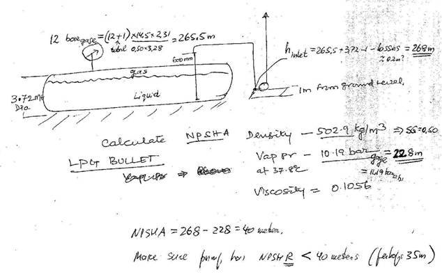
First, convert
everything into same units, say meters. If there is pressure gage on top of the
tank, it would show 12 barg as 265.5 meters, as shown
by calculations, given the specific gravity of LPG as 0.50 (502.9/1000). At the
pump inlet, pressure is somewhat greater – by the level of the full tank, less
the 1 m rise from the floor, so it is 268 meters, assuming hydraulic losses in
the pipe around 0.2 meters (you can calculate these for better accuracy).
The 10.19 barg (11.19 bar(absolute)) would
equal to 228 meters, and thus the NPSHA = 268-228 = 40 meters. The pump you
would select would need to have NPSHR of less then
this NPSHA, - perhaps around 35 meters or so. You also may want to double check
the units of pressure, - are they in gage or
absolute units? – or perhaps a mix (for example, I suspect your 10.19 bar is in
absolute, not the gage units I used)? If not,
convert to the same (consistent) units, and recalculate, following the sequence
I outlined for you.
Note that in order
for pressure in the tank to be 12 barg, temperature
there would need to be less then 37.8 deg.C, otherwise, if you state it is in equilibrium with
the gas, then the pressure would need to be 10.19 barg,
not 12 barg. You need to check that, and redo the
calculations as I showed. There are also examples of similar problems on our
web site, under section Articles or section Q&A. Please also keep in mind
that initially, when the pump first starts, it needs to pull the liquid up the
pipe to prime the line, i.e. the pump needs to be either self-priming, or have
some special ways for pushing the liquid in the tank thru the line, up, and
then to the pump. This is sometimes done by pressurizing the tank with nitrogen
blanket or similar means.
For more
information, you are welcome to attend one of our
Regards,
President /
Technical Director
Pumping Machinery,
LLC
Tel. 770-310-0866
Fax. 770-350-9311
email DrPump@PumpingMachinery.com
Question #119:
We got a tough problem, - can you help? - Suggestions
on a good quality Degreaser? Our applications are wastewater lift stations,
floating grease and such.
Jason
Henderson
Jane, this is somewhat outside my direct expertise, but I will forward
it to some knowledgeable folks at the wastewater lift stations at DeKalb
County, with whom we work on pumps.
They deal with a wide range of equipment, and perhaps can help you out with an
advice.
President / Technical Director
Pumping Machinery, LLC
Mrs. Kisselbaugh,
FOG problems are always tough problems
indeed. I have 65 lift stations and two treatment plants in my system and have
been doing extensive testing of products for Odor Control as well as FOG
removal and elimination. The link below is a natural solution that both
eliminates grease and also reduces odor (most fat Oils and Grease cause odor).
If you tell me what specific problem you are experiencing I may be able to
suggest something better.
www.tersuschem.com/index.php?option=com_content&task=view&id=27&Itemid=28
By the way I graduated from
Regards,
F&T Division Manager
DeKalb County Department
Watershed Management
Question #120:
I know that cavitation starts when suction
pressure drops below vapor pressure. Does a manner of suction pressure
reduction matter? For example, I can
reduce pressure in front of a pump by pinching suction side valve, or – I can
reduce pressure at the supply tank by pulling vacuum. What is a difference? As
I see it, as long as the suction pressure drops to the NPSHR value, cavitation
should start, no matter how I get this pressure. Until
that point, as I also understand it, the flow should
not change. Please help clarify.
Bob Carren
Chemical Plant
Ohio
Bob – there some difference in a
manner of low pressure creation at the pump inlet. However, there are other
factors of interest to review to understand this issue in more depth. Take a
look at one of the live hands-on exercises we conduct during our regular Pump
School sessions: pump suction throttle versus vacuum - why different? -
YouTube– in this exercise, two
tests are conducted: one dropping suction pressure in front of a pump by valve
throttling, and another case by introducing vacuum at the supply tank. In this
example, water is recirculated back to the supply tank (dash line version),
instead of a more common situation where it is pumped from one tank to another:
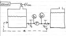
 => would you (not) expect what is shown to
the right – in both cases? (!)
=> would you (not) expect what is shown to
the right – in both cases? (!)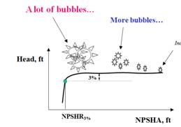
Fig. 1 System illustration
http://www.pump-magazine.com/pump_magazine/q&a/faqq111-120/faqq111_120.htm(Question
#120)
Let’s use this example as a Test Quiz
(correct answer gets you a winning ticket to the next Pump School:
http://www.pumpingmachinery.com/pump_school/pump_school.htm
As suction valve Vs is
throttled, suction gage Ps reads less pressure, and in fact gets
below atmospheric. From what we know happens when suction pressure begins to
drop, - a the flow and head remain constant for some time, until suction
pressure drops significantly, when NPSHA reaches NPSHR, and then the total pump
head begins to drop very quickly. However, as the video on the link shows, flow
starts dropping immediately while the suction gage needle barely moves! – and
yet, no cavitation is observed.
Alternatively, when we keep the
suction valve open, but apply vacuum to the supply tank via vacuum control
valve Vvac – the flow remains constant, as expected, until rather
strong vacuum is reached, and a fully developed cavitation becomes obvious and
strong, with flow (only then) dropping suddenly.
Can you explain why? – should, in both
cases, the flow behave similarly – i.e. staying constant for a long time, and
only starting to be affected at low values of NPSHA (low Ps).
P.S. This test is one of the standard
exercises during our Pump School sessions – for schedule, visit the link above^
The best answers we received are published below,
with a few minor comments following it:
Dr. Nelik:
I watched the YouTube video you posted for the pre-class problem, and I
think I have the solution.
In the first experiment, the pumped flow rate decreased when you
throttled the suction-side valve because closing the valve added dynamic head
to the system. The result is that the operating point moved the left on the
pump curve, and the flow rate decreased.
In the second experiment, the pump flow rate did not change when you
pulled a vacuum on the tank headspace because the pump system is a closed
system. The change of pressure in the tank affected the suction-side and the
discharge-side equally, so no dynamic head or static head change occurred. The
system curve did not move, and consequently the operating point did not move.
However, cavitation became evident (air bubbles in the flow meter) because
reducing the pressure in the tank decreased the NPSHa in the system to the
point that the pump started to cavitate.
I’m looking forward to finding out if I’m correct when I get to your Pump School training
this week. See you then.
Jim Gagnon, P.E.
Senior Engineer
CH2M HILL
Cincinnati, Ohio
Dr. Nelik,
Here is my interpretation of the facts.
The system as it operates use the pump just to provide the
dynamic head losses of the circuit (tank to pump and from pump back to the same
tank - connections in the tank is at the same height so the static head is
zero).
When the vacuum pump is put in service (CASE B), there is
no difference in terms of system itself and the pump still delivers the same
flow (no changes to the circuit - static head still zero and the circuit is not
changed because all valves remained in the initial position). If vacuum is
further reduced and gets low enough, then cavitation will start to take
place (NPSHa approaching NPSHr) and at this point the performance will
start to deteriorate and flow will drop.
CASE A is different because the system is being modified by
closing the suction valve and it is not related to "classic"
cavitation (at -10inHg, assuming that test was done with water at room
temperature water still far away from its vapor pressure). Once valve starts
being closed, system curve "travel" to the left on the pump curve
reducing the flow rate and consequently increasing the head to compensate for
the losses imposed by the partial closure of valve.
The further we throttle the valve, the lower will be the
suction pressure and the system curve moves further to the left of the pump
curve and at some point will eventually reach shutoff resulting in no flow. I
could not observe in the video if there was any signs of cavitation for CASE A,
but if it was present it was related to recirculation cavitation (not the
"classic" one due to the explanation given above).
Generally NPSHr curves do not extend all the way to zero
flow rate. At lower flow rates, NPSHr curve will start rising again. In this
case (to the left of the pump curve, far from BEP) eddy currents begin to form
at the eye of the impeller and initially no detrimental effect is observed but
the eddy currents effectively reduce the flow area which leads to an increase
in velocity of the liquid and consequently increase pressure drop. Thus the
NPSHr increases. When the pressure drop is big enough (approaching liquid vapor
pressure) the pump then will start showing signs of
the "classic" cavitation due to the consequences of
recirculation cavitation.
Respectfully, Rodrigo Cardoso
Bravo Jim and Rodrigo! – good
work, excellent insight!
Normal flow control of the pump/system is done by
closing or opening of the discharge side valve – almost never by its
suction side. Closure of the valve increases the losses across the discharge
valve, and its opening decreases the losses: new system curves are thus created
which intersect the pump curve at a new operating points:

Fig. 2 Connection between
the discharge performance (H-Q) and cavitation (NPSHR)
Now, once the discharge valves “moves” the
pump to a new operating point, its suction
characteristic begins to change – requiring less NPSHR at a lower flow, and
more at higher flow:
Fig. 3 Development of
cavitation
Keep in mind that a Pump (differential!) Head
is a difference between Discharge Head and Suction Head.
If the same pressure reduction is applied to the supply tank and delivery tank
(or as in our example – the same tank), the differential head (pressure)
does not change: added vacuum cancels out on both sides. Both suction
and discharge gage readings change – but by the same amount.
However, if only suction side is affected
(suction valve closure), but the discharge side is forced to remain the same
(the pump discharge side sees the same pressure due to the same tank level),
the differential does change, - i.e. pump head (differential pressure)
increases, and so, according to the H-Q curve, the pump hydraulically moves to
lower flow, - and at lower NPSH required, i.e. farther away from cavitation.
There is a still another little tweak to that, and
at our next Pump School we will discuss how NPSHR curve also changes at low
flow (as compared to how it is shown at the graph here), if certain design
features (which ones) of the pump are modified: http://www.pumpingmachinery.com/pump_school/pump_school.htm
Lev Nelik
Pump Magazine On-Line
January-April, 2014
CLICK
HERE TO SUBMIT YOUR QUESTION