PUMP MAGAZINE: Questions and Answers
(21-30)
Editorial staff
continuously updates Q&A section by adding new questions and answers, based
on our readers’ interest, input and feedback.
*******************************************************************************
Question 21: Hello Dr Pump!
I am making a market research on the application of our
corrosion resistant coating on pumps & valves... I would like to have some
experts' names to contact in that context... Do you have some? Thank you very
much!
Sigrid Jourdain
Bekaert Group Business Development
President Kennedypark 27D
B-8500
Answer: Dear Sigrid,
There is a very significant body of literature on coatings, ranging
from the commercial and trade magazine publications to research journals. Some
companies do their own research, consulting, as well as market their products
and services. Below is just a small sample list of sources, to begin with:
![]() Battelle, Columbus, Ohio, tel.
614-424-4303 – a general research and consulting on materials.
Battelle, Columbus, Ohio, tel.
614-424-4303 – a general research and consulting on materials.
![]() Metco Perkin Elmer, Westbury, NY, tel.
516-334-1300 – coatings applicators
Metco Perkin Elmer, Westbury, NY, tel.
516-334-1300 – coatings applicators
![]() John Crafts, Engineering Consultants, in
Edison, NJ – materials, failure analysis, tel. 201-225-0404
John Crafts, Engineering Consultants, in
Edison, NJ – materials, failure analysis, tel. 201-225-0404
![]() Cincinnati Thermal Spray (CTS, formerly
Holtgren Company), www.cintithermal.com, (e-mail info@cintithermal.com), with locations
in Ohio, North Carolina and New Jersey). The owner and a president of the
former Holtgren Company, Dr. E. Buchanan, tel. 908-686-2332 is a renown expert
in the field of coatings, including diffusion coatings, metallizing,
stelliting, plasma-transfer-arc (PTA), spray- and fuse coatings (braze
coatings), plasma spray, shrouded spray techniques, vacuum plasma spray, laser
coatings, ion formation, and D-Gun (denotation method) high velocity coatings.
He has published numerous articles on the subject.
Cincinnati Thermal Spray (CTS, formerly
Holtgren Company), www.cintithermal.com, (e-mail info@cintithermal.com), with locations
in Ohio, North Carolina and New Jersey). The owner and a president of the
former Holtgren Company, Dr. E. Buchanan, tel. 908-686-2332 is a renown expert
in the field of coatings, including diffusion coatings, metallizing,
stelliting, plasma-transfer-arc (PTA), spray- and fuse coatings (braze
coatings), plasma spray, shrouded spray techniques, vacuum plasma spray, laser
coatings, ion formation, and D-Gun (denotation method) high velocity coatings.
He has published numerous articles on the subject.
![]() Chris Miller, with a US branch of
Saint-Gobain (France) Performance Plastics may be able to assist you, and his
e-mail is chris.i.miller@saint-gobain.com. Chris’ former
affiliation was with DuPont, he has chemical engineering background, published
at International Pump Users Symposium in Houston (paper on specialty
dry-running pump application), and should be able to help you, or point to a
right direction.
Chris Miller, with a US branch of
Saint-Gobain (France) Performance Plastics may be able to assist you, and his
e-mail is chris.i.miller@saint-gobain.com. Chris’ former
affiliation was with DuPont, he has chemical engineering background, published
at International Pump Users Symposium in Houston (paper on specialty
dry-running pump application), and should be able to help you, or point to a
right direction.
![]() Mamat (Morgan Advanced Materials and
Technology), www.mamat.com, could be
another resource for you.
Mamat (Morgan Advanced Materials and
Technology), www.mamat.com, could be
another resource for you.
![]() For a more scientific and
research-oriented work, I recommend Dr. A. Marder, at Lehigh University,
Bethlehem, Pa, USA, arm0@lehigh.edu - examples of
his work are “WC-Co type Thermal Spray Coatings as a Counterface Material for
Adhesive Wear”, “Weld Overlay Coatings for Erosion Controls”, and more.
For a more scientific and
research-oriented work, I recommend Dr. A. Marder, at Lehigh University,
Bethlehem, Pa, USA, arm0@lehigh.edu - examples of
his work are “WC-Co type Thermal Spray Coatings as a Counterface Material for
Adhesive Wear”, “Weld Overlay Coatings for Erosion Controls”, and more.
![]() A company in Israel, SurTech Surface Technologies
uses advanced surface treatment methods for applications of special-purpose
low-friction mechanical seals, balancing drums, etc., - they have strong
industrial affiliation as well as University-backed research. You can contact
them at izhak_e@surface-tech.com
A company in Israel, SurTech Surface Technologies
uses advanced surface treatment methods for applications of special-purpose
low-friction mechanical seals, balancing drums, etc., - they have strong
industrial affiliation as well as University-backed research. You can contact
them at izhak_e@surface-tech.com
![]() Finally, in your own backyard, in Belgium,
you may contact Empo N.V., recently merged with Verder Pump Group, - with years
in pump business, they should be able to further help with materials and
coatings references, as well as share any needs for their pump applications.
Contact them at herwig.vansande@empo.be
Finally, in your own backyard, in Belgium,
you may contact Empo N.V., recently merged with Verder Pump Group, - with years
in pump business, they should be able to further help with materials and
coatings references, as well as share any needs for their pump applications.
Contact them at herwig.vansande@empo.be
![]() Oh, yes – this note just came out - a SSPC
(Society for Protective Coatings) has a National Conference and Exhibit in
Tampa, Florida, November 4-6, 2002, with participants from pulp and paper
mills, chemical, food processing, pharmaceuticals, petroleum and refining,
shipyards, power plants, government, manufacturers, and more. Check with their
site www.sspc.org, or e-mail to
Susan Prokopchak at prokopchak@sspc.org
Oh, yes – this note just came out - a SSPC
(Society for Protective Coatings) has a National Conference and Exhibit in
Tampa, Florida, November 4-6, 2002, with participants from pulp and paper
mills, chemical, food processing, pharmaceuticals, petroleum and refining,
shipyards, power plants, government, manufacturers, and more. Check with their
site www.sspc.org, or e-mail to
Susan Prokopchak at prokopchak@sspc.org
I hope this helps, and gets you started, - let us know if we can
help again,
Dr. L. Nelik, Pump Magazine
*******************************************************************************
Question 22: When pumping liquid up the building, does NPSHA
of a pump changes depending on its location – on the ground, versus on the
roof? Since this is a closed system, how does the pump discharge side affect
its suction?
Answer: This is a very interesting
question, and we thought the subject was generic enough and interesting to make
it into a Quiz (see Quiz #2
under Quizzes Section). What do you think? What would be different with regard
to pump head, and with regard to NPSHA, if the pump installed on a roof, with a
pump leading to it from the ground, versus a pump being on the ground, and
pumping up to a heat exchanger on a roof? What happens when a position of a
heat exchanger changes - on the ground, on a roof, or a side wall?
*********************************************************************************
Question 23: (via Application
DataSheet Request section of Pump magazine)
Name: Susan
Pumped Fluid: water
Flow: 4500 gph (75 gpm)
Discharge Pressure: don’t know
Suction Pressure: don’t know
Differential Pressure: don’t know through a 2" PVC
tube
Specific Gravity: ?
Temperature: 40 - 80 deg F
pH: 6.0 - 7.8
% Solids and Size: 1% solids 1" long
Preferred Materials of Construction: capable of being
wet and not rusting - plastic or stainless
Comments: This pump is to circulate pond water to a
filter system. It needs to pull or push water from a depth of 6 ft to an
external filter system capable of handling 3000 gph of water.
Answer:
Susan,
We have placed your question on the
Pump Magazine site, and would like our readers among the pump distributors to recommend.
We will forward their recommendations to you, and you could contact them for
assistance to supply the pump. They would need to know the discharge pressure,
or at least to make an estimate, in order to size the motor. A local
distributor should be able to do that easily.
Obviously, you are on a right track
already – narrowing down to stainless and plastic. Most likely this will be a
centrifugal pump of one of the two types – either vertical, installed on the
bottom of the pit, with a pipe leading up, and a long shaft, connected to a
motor at the surface, - or a submersible pump, with “wet” motor dipped down to
the bottom of the well with a pump. The advantage of a first type is dry motor,
but a disadvantage is a need to recouple it each time it is pulled up for
maintenance. The submersible motors used to have a problem with sealing system
– if it leaks – bad news for the motor. Today, however, wet motor designs
progressed significantly, and work fine and do not leak. They are also a bit
easier to pull out. My guess is it will be a bout 3-5 hP motor, so somewhat
heavy. Hopefully, of course, it will not need to be pulled out often, and will
work a long time before repairs.
Solids handling could be somewhat an
issue, unless the pump will have inlet screens, to screen them out. Typically,
these are not specialty pumps, but a mass-produced items, so cost will be
probably your main consideration, and you should get a couple of bids, to
compare.
You may be interested to take a look
at another reader’s question (#19) – he used Ebara pump, - although it was a
bigger unit, - but the application had some similarities with yours.
To our readers –
please help out with your suggestions. We will publish the answers, - and,
hopefully, will hear back from Susan how it worked out.
Pump Magazine
*********************************************************************************
Question 24: After reading the Pump
Magazine article, I find them very enriching and am looking forward to more new
technical information.
Could you explain how an ANSI pump impeller clearance
(both open vane impeller with back pump out vane and reverse vane impeller with
balancing holes) setting affect pump performance? What are the advantages and
disadvantages of these impellers?
Thank you,
Best regards
Justus Chew
P.S.: There is a typo error at Articles No. 2. The
denominator of NS formula should be FT3/4, instead of S3/2
.
Answer:
Dear Justus,
We have prepared an article (Article #10) based on your
question. Let us know if this helps.
Also, thank you for pointing out at the error in Article #2. We
made the proper correction per your observation.
Editors, Pump Magazine
*********************************************************************************
Question 25: Dear Sir /Madam
I have following queries regarding the centrifugal pumps
parallel operation.
1) What is meant by designed flow and calculated flow of
a centrifugal pump? I have 3 same pumps with following specs written in a specs
sheet:
Design flow = 500 m3/hr
Head= 5 bar g = 52 M
Calc flow = 360 m3/hr
Suction pressure= 50 M
Shut off head = 54 M = 5.3 bar
Suction = 10”
Discharge = 8”
Pump efficiency= 80%
I am confused, that whether this pump will generate a
flow of 360 m3/hr at 5 bar back pressure, or it will generate a flow of 500
me/hr at this pressure? Actually there are three pumps of same size discharging
in a common header of 16” dia. The flow at the header is 864 m3/hr at 5 bar.
While it should be aprox 1500 m3/hr at 5 bar according to pump designed
specs of 500 m3/hr at 5 bar.
2) Secondly, is there any effect of discharge common
header size on the delivered flow? Suppose the same pumps are pumping the fluid
firstly in the common header of 14 inch dia at 5 bar, and in the second case in
16 inch header pipe at 5 bar , will the flow be same in both the cases
against 5 bar back pressure?
Please note that the pressure gauges (indicating 5 bar) are
installed at the discharge of each pump at 8” discharge lines before entering
into 16” common header.
Looking forward to an urgent and kind response,
Best Regards
Armaghan Yusuf
Answer: Dear Armaghan:
The spec you are
referring to was probably prepared by the original pump engineering company, or
a construction firm. Usually, these specs refer to various pump standards. For
example, API 610 Pump Standard has definitions for various points along the
pump performance curve, such as rated, best efficiency, and normal
point. This can be confusing, but the intent is to make sure pumps do not
operate too far out on a curve, nor too close to the shut-off head.
Paragraph 2.1.12 of
API 610 says “Pumps shall have a preferred operating region of 70-120 percent
of best efficiency capacity…”, and 2.1.13 says that “The best efficiency
point…shall preferably be between the rated point and the normal point”
Let’s see how this
could be related to your case:
The design flow is
most likely the same as best efficiency conditions, i.e. 5 bar at 500 m3/hr. We
know the shut-off head of 5.3 m, so the first thing we do is sketch out the
approximate curve through these two point:

Usually, the operating
point is a little to the left of BEP. This is what the spec seems to call a
“Calc flow”. From the curve, the head at that (operating) flow of 360 m3/hr
would be between 5.0 and 5.3 m – say it is about 5.1 m.
Next, remember that a
pump operates at the intersection of a pump curve H-Q and a system curve (look
up several other Articles
within Pump Magazine on that subject. For a parallel operation, we need to add
the flow of each pump at a given head. Do that for several heads, and you get a
combined curve. Let’s show as(1) a single pump curve; (2) for two pumps
together, and (3) for three pumps.
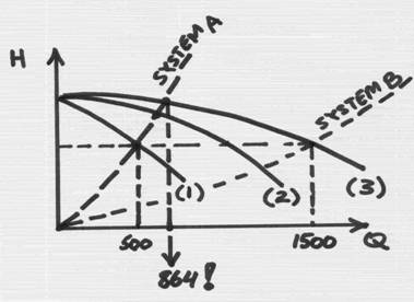
For your system, there
is probably very little static head, and mostly the system curve is friction
losses of pipes – shown as “System A”.
You can see now why you
do not get to 1500 gpm – a given system curve intersects the curve for one pump
at 500 gpm, a little more for two pumps, and a little more yet for three. But
the system curve keeps rising up quickly, and does not stay on flat (actually
it would be if you system was mainly static head, as it would be if pumps were
pumping against a certain level).
This is why you are
getting only 864 m3/hr, and not 1500 m3/hr. In other word, no matter how
“strong” the pumps are, or even how many of them! – they can “push” only so
much flow through, as the system will allow!
You are correct in
thinking that the size of the pipes would effect this. The smaller the pipe –
the more friction, and the stepper is the system curve. Conversely, a larger
pipe has less friction. To get to 1500 gpm, the pipes would need to be larger –
see System B curve.
Or, you may have a
combination of friction losses and static head, which would make system curve
offset along the head-axis by the amount of static head, and then a parabola
will continue on, as a function of flow (again, take a look at couple of
Article within the Pump Magazine on that).
The only still
confusing thing is why the discharge gages by the pumps read 5 bar. Per sketch
above, this is only when one pump operates. When a second, and then a third
pumps come in, the sketch indicates the head should be more then 5 bar.
However, note that the head can not be more then the shut-off value of 5.3 bar.
This is because the slope of the H-Q curve is usually very small for centrifugal
pumps. So, perhaps, the actual value is something like 5.1 or 5.2, but recorded
as 5.0 by the operators, since it is so close, and is approximated.
Now that you have
data, you may fine-tune the sketch to reflect your actual installation more
accurately. You should be able to estimate the size of the pipe you need by
keeping in mind that the pressure loss is a function of the velocity in the
pipe squared. You already have a system curve for your existing pipes and
elevations. Re-calculate the new velocity in a larger pipe, squire it, and
compare to the same for small (original) pipe. The ration would be the change.
That will give you new points to draw a new system curve through, and then –
get an intersection with the three-pumps curve. Or, you may consider having a
consultant take a quick look to make sure. Better yet – you may ask the
original system contractor to show you their original system calculations and
curves, - if they have them.
We hope this helps. As
you can see, a simple sketch may sometimes tell the story.
Dr. Lev Nelik, P.E.,
Apics
Editor, Pump Magazine
*********************************************************************************
Question 26: I'm looking for contact
information for Worthington Corporation in Harrison,
New Jersey. Can
you help me? Thanks.
Melissa Arrasmith
System Engineer
Tennessee Valley Authority
1101 Market Street, LP 2L-C
423-751-7578
Answer:
Dear Melissa,
We have reached a former President of the Hydraulic Institute,
Mr. John Fenlon, to help shed some light on the past history of the pump
manufacturing world, as well as, hopefully, to get some current links to the
matter, which could help you. It so happens that John worked at Worthington
Pump corporation around 1980s, as a Vice President of Sales and Marketing, and
was able to provide some brief background which could be at least a start for
you to help find the answer.
In the last decade, the world of the pump manufacturing community
has had its share of “turbulence”, to say the least. Companies merged,
restructured, sold off divisions, changed names, - but the dust and commotion
still do not seem to have settled down. Some years ago, Worthington had become
part of Dresser, which then through a series of transformations and mergers has
eventually become a FlowServe Corporation, which also includes former
Ingersoll-Rand, Byron-Jackson, and a whole slew of others.
Worthington’s big competitor used to be Ingersoll-Rand, -
particularly in the area of large (or even “huge”) pumps, such as multistage
boiler feed barrel pumps, vertical circulating pumps, and most notably, pumps
for the US Navy. Headquartered in New Jersey, the two companies were known for
their excellent quality, superior engineering, and worldwide presence. With
dismantling of the Worthington operations, many of its employees went to work
to the “relatively-near-by-and-near-same-products” - Ingersoll-Rand, at its
Phillipsburg, New Jersey plant. You may try to call there, and hopefully locate
some of the people who may still work there. Unfortunately, with the subsequent
downsizing of the IR operations and reallocation of the work to other plants
within the FlowServe, the number of people at the Phillipsburg plant has been
substantially reduced, - but, you could be lucky.
The number is 908-859-7000, - for the IR’s switchboard.
Interestingly, “the recent rumor is” that the former IR plant in
Phillipsburg may get another opportunity for a “new beginning”, - and if so,
your inquiry toward that direction may make even better sense. If you are
looking for a replacement of an old Worthington pump, - the new Ingersoll-Rand
operation in Phillipsburg might then be back in business and manufacturing
similar, although not identical, units – and they may help you with the replacement,
or retrofitting.
Good luck! – we hope this may help, - plus, by a note to our
readers – if anyone has more information for Melissa regarding Worthington –
please let her know.
Lev Nelik
Editor, Pump Magazine
…and more to the above from Luis Rizo:
Hi Melissa.
I was a Worthington employee in the 70’s, and the company ceased
to exist after a series of takeovers.
The first was McGraw Edison, an electrical conglomerate, who sold the
pump business to Dresser. Dresser Industries then merged with
Ingersoll-Rand. Call your local IR
Distributor and see if he has some contacts.
I have an old PSI (Worthington’s old pump tech
manual/catalog. If you have a particular
question on a pump, I may be able to find it there. Let me know.
Luis Rizo
*********************************************************************************
Question 27: Dr. Pump, - thank you for your assistance and kind
help.
I have another question:
1. When we calculate the dynamic head (v2/2g) is it in
absolute pressure or gauge?
2. Can you write an article on how to do some
maintenance jobs, such as, adjusting the endplay, checking the alignment and
other maintenance jobs that every engineer should know?
I know that what I have asked is too much on you, but I
really would thank you for any help you can provide.
Thanks again & regards,
Abdallah al-Ghilani
Answer:
Dear Mr. Al-Ghilani:
If you substitute the units, you will get feet of head:
(Ft2/s2)
/(Ft/s2) = FT (or meters if in English units)
Dividing by the
appropriate constant gets us pressure units. For example, dividing by 2.31 x SG
gets psi.
Typically, the gages
on the suction and discharge side of a pump read pressure in psi (or bars
if in non-US system) – and, these are usually in gage (e.g. psig)
units. There are gages that read absolute pressure (psia)- they are more
typically on a suction side, where the pressure is lower. The correlation is
straightforward:
PSIG = PSIA + 14.7 (in US system)
The idea is that the
gage shows 0 (zero) at normal atmospheric condition, - which is 14.7 psiA
(absolute). This way, a 3 psi vacuum would technically be 14.7 –3 = 11.7
psiA, or – (minus) 3 psiG
So, the “gage”
pressure gage dial show “0” for 14.7 psiA, and the “absolute” pressure gage dial
shows “0” at 0 psia (absolute vacuum).
To calculate pump
head, velocity heads at suction and discharge must be accounted for. These do
have neither “gage”, nor “absolute” units. The total pump head is the difference
between the discharge head and suction heads. Each of those has units – either
gage, or absolute – depending how it was measured (what type of gage used) –
but the TDH (differential head, or a pump head as it is called).
For example, say the
discharge gage reads 100 psiG (100x2.31/1.0 = 231 feet(g), for water at
SG=1.0), and velocity head at that location is 10 feet. Say, suction pressure
is 20 psiG (20x2.31/1.0 = 46.1 feet(g), and suction velocity head is 5 feet.
Then, TDH = (231 + 10)
– (46.1+5) = 199.9 feet
There are several
Articles in Pump Magazine, which shows more examples, and also take a look at
Quizzes Section, - for additional insight.
Regarding
you suggestion about the publications on maintenance related issues – it is an
excellent idea, - we agree, and have been asked for this numerous times. We are
starting a Pump Maintenance and Reliability Section of Pump Magazine. We
hope you will enjoy it, as well as contribute with your ideas.
Best regards,
Dr. Lev Nelik
Editor, Pump Magazine
P.S. By the way, -
don’t worry about your questions! – they are good! There are no bad
questions! – and, if you need to know, - we will help!
*********************************************************************************
Question 28: Dear Pump Magazine,
I am trying to specify a pump system, capable of pumping
an epoxy resin. I need to deliver the two components of the resin to a static
mixing head which is located at a depth of 32 metres subsea close to the point
of delivery of the mixed resin. The static mixer is of the Kenics type and I`m
looking at a 1.5" version. It would seem due to the high viscosity of the
resin that a lobe type positive displacement pump would
be most suited to the application.
The two components of the resin are required to be mixed
at a 1:1 ratio by weight, with parts being 1.5 and 1.6 density respectively.
The viscosity of the components is 1260 and 2480 poise respectively.
Total volume of resin required for the task is 500
litres. The main problem is delivering this amount to the delivery point within
the curing time of the resin before gelation has progressed to make it
unpumpable, i.e approximately 45 mins. I will be injecting the resin into the
base of the structure and purging out any contained seawater. The structure is
approximately 4 metres high so the total mass of resin will be above the
injection point.
To me, the most difficult point is how to start and get
some ideas, so that the rest of the system can be tailored around this. I will
appreciate your and your readership’ assistance if possible.
Regards,
Dave Vernon
STATS (UK, Ltd.
Answer: Dear Dave,
We have
posted your request in a Distributors Section of the Pump Magazine, to see if a
distributor in your area, that carries the types of pumps you need, may
assists. We will forward to you their response as soon as we get it.
You are
right - with viscosity over 50-100
centipoises, a positive displacement pump is used. In your case, 2480 poise (or
248,000 cP) is significant. Lobe, gear or progressing cavity rotary pumps would
be good candidates to consider. Your flow rate is about 500 liters per hour, or
10 liters per minute. You need to calculate the discharge pressure, against
which the pumps will be delivering the resin. That would consist of friction in
a pipe (probably significant, because it is so viscous), plus any resistance at
the injection point, and to overcome the losses through the mixer. I think you
will find that differential pressure will be around 100-150 psi, and the
horsepower required probably around 10 HP per side, but this is a very rough
guess only.
If you
can accept a close, but not exactly the same volumetric flow rate for each
stream, perhaps an interesting solution might be to hook up the pumps on both
sides of the double-extended-shaft motor. That way, the pumps will be rotated
at the same speed, and, if they are the same size, they will produce the same
volumetric flow – although the mass flow will be different due to the Specific
Gravity differences (1.6 / 1.5 = under 8% accuracy, if acceptable).
At this
level of viscosity, the pumps will be running very slow – perhaps 50 RPM, or
even less, which means you might need an inverter-duty motor, which has a fan
running independently of the pump speed (obviously with a double-extended-shaft
this makes it more difficult). Otherwise, the motor, not having enough cooling,
may overheat.
I hope
these notes help a little, and also, let’s see what the distributors will
advise.
Regards,
Lev
Nelik
Pump
Magazine
*********************************************************************************
Question 29: Dear Pump Magazine,
I enjoyed reading the Article #6 “Is 316SS soft or
hard?!”, and learned something new to me. I would like to know more about the
steel properties and composition. Please let me have the details regarding the
metallurgical properties of steel and any other related information.
Regards
Milan
Answer:
Dear Milan:
316 stainless steel is probably one of the most popular materials
among the austenitic stainless steels. It contains 16-18% chromium, 10-14%
nickel – the main allying elements in it. It also has 2-3% molybdenum, and
carbon is limited to under 0.08%. If carbon is limited down to 0.03%, the steel
becomes 316L.
Austenitic stainless steels (sometimes referred to as “18-8”
grades (18% Cr, 8% Ni), have excellent properties with regard to corrosion
resistance. They can not be hardened, except by cold work, - which is what
makes them resistance to cavitation, - as you learned from Article #6.
The other important groups of stainless steels are Martensitic and
Ferritic. You may look into an Answer to Question #21 of this section, for more
information, as well as additional source references.
Pump Magazine
*******************************************************************************
Question 30: Dear Sir,
I am a pump engineer and I have a question regarding
431ss material. Is this material magnetic or non-magnetic? If yes, please
explain.
Thanks and best regards,
AHMED SOBHI
SALES MANAGER
ROTATING EQUIPMENT DIVISION
DAFF TRADING & OIL SERVICES EST.
POB 7399 ABU DHABI
Answer: Dear Ahmed,
Interestingly, a previous question was regarding also about
metallurgy, 316ss (see Question #29 above)!
Series “400” is martensitic stainless steel, and it
IS magnetic, while series “300” is austenitic
and it is NOT magnetic. What makes stainless steel magnetic or not magnetic is
its composition (alloying elements) and the manner (heat treat) in which it is
produced.
The main alloying element in 431ss is Chromium – roughly 16%,
which makes it resist corrosion rather well, certainly better then plain carbon
steel. And, it also makes it hardenable, which is why martensitic alloys are
very good for pump shafts, for example. Martensitic alloys are strong.
When either stainless steel is being initially cast at the
foundry, it starts off having austenitic structure at high temperature, while
being cooled after poor. As it cools down, austenite begin to transform to
martensite, which happens around 770 OC. Certain alloying elements
can delay or prevent such transformation. Chromium and Nickel are among such
elements. Metallurgists use so called Schaeffler diagram, which shows
“Nickel-Equivalent” and “Chromium-Equivalent” contents, required to keep the
resultant alloy in martensitic, or austenitic, state. It roughly looks like
this:
As you
can see, it is the addition of Nickel that keeps the 316ss alloy in austenitic
zone. The 431ss does not have it, only Chromium, - and so it transforms into
martensitic structure.
Often,
equipment inspectors use a quick-test, by sticking the magnet to a part, to
make they are looking at 316ss part – if the magnet sticks – watch out! –
something is wrong. However, once in a while, the magnet feels like it pulls
toward a 316ss part, although just a “tiny little bit”, certainly not strong at
all. This could indicate some minor amount of residual martensite in the
structure.
The
next time you are near the metal part – touch it with a magnet!
Good
luck!
Pump
Magazine
A Thank-You
response from the reader:
Dear
Lev,
Thaaaaaanks a lot for your
valuable & worth help.
THANKS & B.R
AHMED SOBHI
SALES MANAGER
ROTATING EQUIPMENT DIVISION
DAFF TRADING & OIL SERVICES EST.
Dear Ahmed, - you are welcome! We are glad to hear it was helpful,
and appreciate your note. As we
continue to receive comments from our readers, we update the information. Here
is a latest update per one of our readers’ perceptive note:
Whilst reading the list of
questions and answers I came across a possible mistake in question 30 where the
Chromium equivalent is calculated: should it not be: %Cr+%Mo+1.5x%Si+0.5xCd
(Cadmium)? - and not 0.5xCb as in the explanation?
Regards
Craig Winterburn
Fluor Daniel Secunda
Mechanical Design Engineer
Pump
Magazine has asked Steve Morrow, who is a Global Manager of Materials Technology
with ITT to comment. This is what he
said:
There are many expressions for chromium
equivalent and nickel equivalent depending upon whose you use. Schaeffler -
Schoefler and Delong diagrams to name a few. Delong's diagrams include Nitrogen
effects into the Nickel equivalent expressions.
For example the Schaeffler diagram showing
the amount of ferrite and austenite present in weldments gives:
Chromium equivalent = %Cr + %Mo + 1.5x%Si
+ 0.5x%Nb (or Cb) Note: Nb (Niobium) and
Cb (Columbium) are the same element with dual name! Nickel Equivalent = %Ni +
30x%Cr + 0.5x%Mn
The Schoefer diagram for estimating the
average ferrite content in austenitic iron-chromium-nickel stainless castings
is given in ASTM A800 along with the diagram for Creq/Nieq ratio. The ferrite
content of castings is estimated from the composition ratio of "Chromium
equivalent" (Creq) to "nickel equivalent" (Nieq). The equations are slightly different
based on Schoefer as follows:
Chromium equivalent = %Cr + 1.4x % Mo + 1.5x%Si + %Nb (or Cb) - 4.99
Nickel equivalent = %Ni + 30x%C + 0.5X%Mn + 26x(%N - 0.02%) + 2.77
Ferrite content in weldments and castings
is determined primarily by the balance between ferrite and austenite
stabilizers or elements that tend to form ferrite and austenite. By adjusting the ratio of ferrite stabilizers
(Cr, Mo, Si, and Nb or Cb) to austenite stabilizers (Ni, Mn, C, and N) the
ferrite content can be controlled and can be estimated using the Schoefer
constituent diagram relating ferrite content in castings to chemical
composition, which is an adaptation of the well known Schaeffler diagram
developed for predicting the microstructure of stainless weldments.
Although the Schaeffler, Schoefer and
Delong diagrams all provide reasonable accuracy, it is recommended that
castings be evaluated using the Delong diagram, even though it was originally
intended for weld metal deposits and includes effects of nitrogen. The Delong diagram consistently provides the
most accurate prediction of delta ferrite in cast austenitic stainless steels.
Because chemical composition influences
microstructure, a number of empirical relationships and constitution diagrams
have been developed over the years to predict microstructure. In all cases the Chromium equivalent and
Nickel equivalent has been used to predict the effect of various alloying
additions on the ferrite forming and austenite forming relationship. Considerable disagreement still exists
regarding these equivalency relationships and formulas. The Schaeffler diagram was developed in the
1940's to predict weld microstructures.
This was refined by DeLong and refined by the Welding Research Council
in 1988 and again in the WRC - 1992 diagram.
Following is summary of some of these
relationships for chromium and nickel- equivalency, many other modified
expressions exist:
Schaeffler - year 1949
Chromium Equivalent = Cr + Mo + 1.5Si +
0.5 Nb
Nickel equivalent = Ni + 0.5Mn + 30C
DeLong - year 1956
Chromium
Equivalent = Cr + Mo + 1.5 Si + 0.5 Nb
Nickel Equivalent = Ni + 0.5 Mn + 30C +
30N
Hull - year 1973
Chromium
Equivalent = Cr + 1.21Mo + 0.48Si + 0.14 Nb + 2.27V + 0.72W + 2.20Ti +
0.21Ta + 2.48Al Nickel Equivalent = Ni + (0.11Mn - 0.0086Mn squared ) + 24.5C +
14.2N + 0.41 Co +0.44Cu
Hammar and Svennson - year 1979
Chromium Equivalent = Cr + 1.37Mo +1.5Si
+2Nb +3Ti
Nickel equivalent = Ni + 0.31Mn + 22C
+14.2N +Cu
Siewert - year 1992
Chromium Equivalent = Cr + Mo + 0.7Nb
Nickel Equivalent = Ni + 35C +20N + 0.25Cu
Cordially,
Stephen J. Morrow
Global Manager of Materials Technology
ITT Industries
Industrial Pump Group
Steve, - thank you. This was
enlightening and helpful.
Lev
Nelik
Editor
Pump
Magazine
CLICK
HERE TO SUBMIT YOUR QUESTION