 Pump
Magazine On-Line
Pump
Magazine On-Line

INDUSTRIAL DIGEST
|
INDUSTRIAL DIGEST
|
|
|
Article 54: Power Plant Transients – Why Deaerators Causes Pump Trips - Part 2
Last month we reviewed what happens to a boiler feed pump during the plant transients. We went thru some calculations to see what happens when pegging steam supply to the deaerator is cut off (causing DA pressure to drop) but condensate continues to flow, cooling the DA. We saw that the resultant two-phase fluid in the DA would contain a small vapor fraction (by mass), but the volume proportion of it is huge. The evolving vapor, being sucked to the downcomer pipe, combined with the lowered suction pressure at the pump inlet, can result in a pump trip due to insufficient NPSH, as well as high vibrations and other nasty things that can damage the pump. The essence of the process was shown in a video at www.pumpingmachinery.com/pump_school/pump_school.htm (Click on PVA module #8. It would also be helpful to obtain a last month copy of P&S article to review, as it’s illustrations and data make an integral connection to what we will cover now. The accompanying video for that is at the same link, but as PVA module #9).
As we discussed last month, the cause of the problem was a flashing of the DA. This month, however, we will see what happens if the downcomer is connected not to one, but two pumps, both initially running before the plant transient event (such as, for example, a load rejection during generator trip).
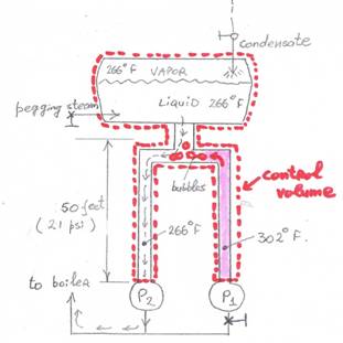
We will assume that Pump #1 was driven by an auxiliary steam turbine which has just tripped (auxiliary steam cut off) after the plant event, and the entire suction header of pump #1 retains the initial 302 deg. F water, trapped by the pump’s valve. We will also assume that all piping is well insulated and there is no heat loss to the surroundings. The pump #2, however, is still running so far. As the DA cools down it continues to feed the still running (motor driven) pump #2 with water at the same temperature as the DA, and thus cooling at the same rate. The 50 feet of static head (approximately 21 psi) provides sufficient suction pressure at the pump entrance (39+21 = 60 psia), above the vapor pressure (39 psia) of the 266 deg. F water.
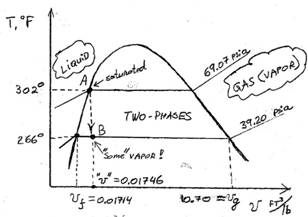
For the fluid in the suction header of the idling pump, the news are not as good: 302 Deg. there require 69 psia as shown at the T-v diagram, but only 60 psia actual is available, and this hot liquid water would want to flash into a vapor phase, i.e. steam. A transformation from liquid to vapor is a complex process, and depends on many factors, such as pressure, availability of volume to expand into, insulation (adiabatic/isentropic process), conduction between adjacent media (such as a colder water adjacent to it at the neighboring pump #2 plus the DA water), etc. For our example, let’s assume the “control volume” consisting of DA plus both headers is constant, i.e. a thermodynamically constant volume process. As the liquid in header #1 tries to expand into steam, it will first encounter a cooler water at the junction to the piping to pump #2, thus a 302 deg. F steam meets the 266 deg. F liquid.
According to thermodynamics, a transformation of vapor to liquid, upon encounting a colder liquid is almost instantaneous (milliseconds). The heat vapor will cool it to liquid, but it will also heat up the cooler water at the pipe #2. Eventually, the 302 deg. F fluid would cool down to 266 deg. F, and will become in thermal equilibrium with pipe #2, both at 266 deg. F, assuming all other parameters remain the same.
The question is whether the heating effect of the hot water on cold water that flows to pump #2 be enough to raise its temperature above saturation temperature to cause it to likewise flash into steam, or at least become hot enough for its vapor pressure reduction sufficiently to reduce NPSHA at pump #2 and cause its cavitation and perhaps trip.
Let’s consider an extreme scenario where both legs (assume equal volumes) of water instantaneously mixed. That would make the temperature in both equal as (266+302) / 284 deg. F (not even considering further cooling by the incoming DA water), with 60 psia suction pressure at the pump inlet. Per thermodynamic tables, at 284 deg. F the saturation pressure is 52 psia (ref. [1]), i.e. still 8 psi below the available 60 psia. Granted, that for a pump to experience cavitation the pressure does not need to be exactly at vapor pressure, to allow some reduction from the usual point of measurement to the area where the pressure actually does drop to vapor pressure (typically right at the in tips of the impeller blades). The 8 psi is roughly 20 feet of NPSHA or so, and is typically sufficiently greater than the NPSHR of a typical boiler feed pump – particularly considering the extreme scenario of the entire column of hot water in pipe #1 instantaneously transmitting all of its heat to water in pipe #2. In reality, however, this transformation would be much less dramatic, more gradual, and in smaller chunks, plus additional cooling by the continual resupply of the even colder water from the DA, thus effecting the temperature of the colder water negligibly.
The possibility of vapor floating up to the DA and choking off the supply of water to the pump #2 can still be considered, although as mentioned, vapor transforms back to liquid when encounting cooler regions almost instantaneously, and thus while possible, unlikely.
In summary, the main effect on pumps cavitation during power plant transients is caused by the behavior of the deaerator (which was discussed last month), and not likely the adjacent piping with trapped hotter fluids in them. Obviously, each case is different and the results could be different at other plants, different sizes of the piping and deaerators, their designs, bends and turns of pipes, pump speed, design, flow, insulation details, and so on.
Let us know your own experience with plant transients - a fascinating topic, and of great importance to plants reliability and availability of power.
Fig. 1 T-v diagram, showing thermodynamics of the transient at the DA and piping Until we meet again (perhaps at the next Pump School!) – Keep-on-Pumping!
References 1. Cameron Hydraulic Data Book, 19th Edition, 2002 2. R. R. Cranfield, “Studies of Power Station Feed Pump Loss of Suction Pressure Incidents”, ASME, Journal of Fluids engineering, vol. 110, December 1988
Dr. Lev Nelik, P.E. Editor, Pump Magazine On-Line January 2015
Feedback from the readers:
Dr Nelik,
I read your online articles about "Power Plant Transients – Why Deaerators Causes Pump Trips". It will be very interesting to read other feedback concerning the handling of power plant transients.
The following comments relate to the scenarios described in articles #53 and #54. Steady flows to and from the DA (deaerator) and gradual isentropic thermodynamic changes from the high to low temperature/pressure conditions are assumed. A gradual power plant cool down period after a shut down event may mitigate any tendency for general or local flashing.
From article #53 at point "A": * DA (deaerator) total tank volume V = 20,000-gal = 2,674-ft^3. * Tank liquid (water) volume Vliq = 10,000-gal = 1,337-ft^3. * Mass of tank liquid mliq = Vliq / vf = 76,564-lbm. * Mass of tank vapor mvap = 0-lbm (all mass is saturated liquid at vf). * Total mass of tank contents M = mliq + mvap = 76,564-lbm. * Using the above values, the calculated specific volume should agree with the T-v diagram at point "A". However, calculated "v" = V/M = 0.03492-ft^3/lbm. This value is greater than vf = 0.01746-ft^3/lbm from the diagram. Since the vapor volume Vvap = mvap x vg = 0-ft^3, the analysis might be conducted by assuming that the total tank volume revV = Vliq + Vvap = 1,337-ft^3. In other words, assume the total DA tank volume is 10,000-gal and completely full of of liquid (water) at "A". Then, "v" = revV/M = 0.01746-ft^3/lbm = vf at "A" on the diagram.
Using revV and "v" for calculations at point "B", X = 0.003%, vapor mass mvap = X x M = 2.3-lbm, vapor volume Vvap = mvap x vg = 24.5-ft^3, liquid mass mliq = (1-X) x M = 76,562-lbm, liquid volume Vliq = mliq x vf = 1,312.3-ft^3. Therefore, the total volume and mass of the tank contents remains the same. However, the vapor volume has increased by the same amount as the liquid volume has decreased. The less-dense vapor must occupy a larger space than the reduction in liquid volume. Since there is no additional tank space to occupy, some liquid may be expelled from the 10,000-gal DA or excess vapor pressure might activate a relief valve.
Expelled tank liquid may imply that, for this scenario, the total mass of the DA tank contents decreases at point "B": specific volume at "B" is greater than at "A". Using "vb" = 0.018-ft^3/lbm at point "B", the calculated vapor volume is now about 66-ft^3 at "B" compared with 24.5-ft^3 if "v" = 0.01746-ft^3/lbm. Since the new liquid volume is now 1,312-ft^3, about 41-ft^3 would need to be expelled from the tank at "B". That is, 66 + 1,312 - 41-ft^3 = 1,337-ft^3 = the tank volume.
However, I would not expect a DA tank to be either half-full of liquid without any vapor or completely full of liquid. A more-likely location for point "A" might be to the right of the saturated liquid state where a 2-phase liquid and vapor state exists: point "A1".
The originally calculated specific volume, "v" = 0.03492-ft^3/lbm, represents a liquid and vapor state at 302-degF. If this value is chosen, a new set of values can be determined at "A1" and "B1": X = 0.17% at "B1", ΔVvap = +23-ft^3, and ΔVliq = -23-ft^3. In this case, the vapor has enough room for expansion going from a calculated 1,341-ft^3 at "A1" to 1,363-ft^3 at "B1". However, even though the calculated liquid volume has decreased at "B1", the corresponding liquid mass has increased. This seems unlikely.
After some trials, it was determined that reasonable changes in volume and mass occurred if the specific volume is greater than about 0.29-ft^3/lbm for the given data in this article. If another specific volume such as "v" = 0.5-ft^3/lbm is chosen, another set of liquid and vapor state values can be determined at "A2" and "B2": X = 4.52% at "B2", ΔVvap = -1.33-ft^3, and ΔVliq = +1.33-ft^3. In this case, the vapor volume has contracted going from a calculated 2,587-ft^3 at "A2" to 2,586-ft at "B2". Now, the calculated liquid volume and mass have both increased at "B2" while the calculated vapor volume and mass have decreased at "B2". Vapor condensation, from state "A2" to "B2", is now the result. This seems to be a realistic outcome after slowly cooling. Although it should be noted that, with "v" = 0.5-ft^3/lbm, there is a substantial difference in liquid and vapor mass and volume values when compared with the original calculations from above.
After an emergency trip situation, there may be ongoing automatic and/or manual adjustments as various plant elements (e.g. DAs, pumps, etc) react to changing system conditions. If the liquid+vapor mass (M), within a fixed-volume DA tank, can decrease or increase in response to some of these changes, maybe the specific volume (=V/M) is not necessarily constant at different thermodynamic states.
Aside from the dynamics occurring inside the DA tank, I would expect that any significant NPSH problem at the pump suction might be attributed to entrained air, instead of water vapor, being transferred from the DA liquid to the boiler feed pump. Before being shut down, the injected "pegging" steam might have removed most of this air.
In article #54, I would not expect a significant problem at pump #2 from an interaction at the junction of its header and the hotter liquid in header #1. If the liquid in header #2 is gradually cooling and flowing past the junction, the temperature difference at a junction may be too gradual for a flashing reaction. However, for pump #1, if it is again started with its header full of 302-degF liquid and only 39-psia available at the junction, there might be an insufficient NPSH condition as pointed out in the article. Maybe pump #1 would be able to pass the 50-ft header full of hotter liquid quick enough to avoid any significant damage or pump trip.
Of course, the above analysis and commentary are based on simplified ideal conditions with gradual thermodynamic changes. Feedback from readers that have experience in power plants and the effects of transients on the pumps could be very interesting and insightful.
Regards, Lee Ruiz Oceanside, CA
Lee – thank you for your comments, and obviously very diligent and methodical calculations. I have a few notes to your comments:
1. Your assumption of a process being gradual and isentropic cannot be assumed. It is highly transient, and in fact one of the reasons it is not easy to calculate. There are several thermodynamic sub-processes in action, highly time dependent. There is convection from hotter liquid to colder, phase transformation, cooling of the vapor that is evolving right back into liquid phase as it tries to rise thru the colder liquid layer. Perhaps the only safe assumption for the process if it being adiabatic, assuming no heat loss thru the pipe to the surroundings due to a thick insulation.
2.
My assumption of
point “A” being liquid occupying half of the tank space, and zero vapor
above it is problematic. A complete absence of vapor in the space above
liquid is impossible, as it would imply full vacuum, while we know the
actual pressure of significant. “Something” must be present above the liquid
surface to maintain pressure, be that injected steam, air, or any other
media. For fluid in the DA being exactly at the saturation curve, or into
subcooled region, would, imply that of course, but we would need to
understand more precisely the specifics of the DA design, to explain what
keeps the void above liquid at pressure in such case. Your note is very well
placed that if we instead make a very slight adjustment to starting point
“A” as being slightly into a 2-phase region, this difficulty immediately
disappears, as now the entire space above liquid is vapor, and the combined
volume in the tank can be treated indeed as the entire tank (20,000 gallons)
instead of half of it (10,000 gallons), and the “total” combined specific
volume would be total tank volume divided by total mass (which at point “A”
is mostly liquid). That would make total combined volume double of that if
we used only half the tank. It does not really effect things for point “A”,
but when going to point “B” makes things easier, as we now have a total
volume of the entire 20,000 gallons (or whatever it is in cubic feet) filled
with a “mixture” – some liquid, and some (above it) vapor. From there, 3. The assumption of the entire system being a constant volume is probably good, as I did. Otherwise, it is impossible to make any other reasonable assumptions. For example, we cannot assume things (transients) happening at point “B” as constant pressure, - as would be, for example, if the tank had a free heavy lid which would by its weight apply constant pressure, and the expanding volume of vapor would move the lid up, way up. Our tank does not have boundaries that can move. The only openings are to the condensate piping, and thru the running pumps, but those are essentially also closed (by running water thru them). 4. For case #54, - as I explained in my article and video accompanying it, vapor “wants” to expand according to a new pressure to which (suddenly) the surface of the DA is now at (point “B”). But it is not a steady state process, and things are really transient: as vapor “wants” to form and float up, it encounters a colder layer above it, and condenses back to liquid, - almost instantaneously – certainly at many orders of magnitude faster than it take for vapor to travel thru the suction header of the running (colder) pump to reach its entrance. Instead, what likely is happening is convective cooling of the hotter leg by the colder leg via such attempted vaporization and re-condensation. A good way to visualize this in a simplified way is as show below:
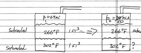
Say you have two layers of fluid, equal volume for simplicity, separated by a very thin membrane. Initially, say 69 psi is enough to keep both liquids subcooled (the lower layer is closer to flash to vapor, but does not – still very subcooled, albeit not as subcooled as the upper layer). Suddenly, pressure at the surface drops to 50 psi, - at which, let’s say, the top layer still subcooled, but the bottom layer belongs to the vapor phase. Will it immediately flash out to many times more vapor volume? If so – where will it go? Assume also the membrane is very thin and raptures as vapor forms (or, say, we simply yank it out quickly). The “attempted bubbles” trying to form at the lower layer would have to meet the colder layer and get back to liquid form. This will go on for some time, - and eventually, both fluid would mix, and the average temperature (266+302)/2, and if at 50 psi is in a vapor region - it will turn to vapor and fill the entire can, otherwise it will remain in liquid form. If the can if very tall, - there will be more space for vapor to form (if it corresponds to vapor condition), i.e. the taller the vessel, the lower the specific volume – i.e. same mass filling larger space. Initially, however, all was in two liquid layers, - but after the drop of pressure (and if the new condition is vapor phase), the vapor will expand to take up the complete volume.
My paper (#54 case)
shows that, for the conditions used in the example, the resultant
temperature, after both columns of liquid came to average temperature –
still no 2-phase situation exists, and thus no vapor, i.e. no cavitation,
and so no NPSH problem. However, the real situation is even more towards the
fact that no vapor would reach the running pump: because the colder column
is not even statically sitting there getting mixed with the hotter liquid.
Instead, as vapor wants to form and transmit its energy to heat up cooler
liquid, - that liquid is actually in motion, taking “a somewhat” heated
chunk and moving it towards the pump, - so that by the time this little
chunk flows thru the entire length of pipe, the resultant raise in
temperature of the flowing liquid is miniscule – thus we are not even close
to heating the cooler leg substantially, - i.e. it is a DA temperature that
would dictate the temperature of fluid reaching the running pump.
Let me know if any additional questions or comments. This is a very interesting subject indeed, and unfortunately largely not clearly understood, as few people took trouble, so far, to go thru the numbers, including simplifications we have covered here, as well as additional corrections by adding other factors which we have not yet accounted. Thermodynamics of transient conditions is not simple. Which is why pumps continue to have problems.
Lev Nelik PML
Dr. Nelik,
Thank you for your informative and detailed response. It is indeed a challenge to attempt a simplified evaluation of power plant transient conditions. Other than relevant on-site reports, a representative CFD model and analysis might be interesting. Some additional speculative comments are offered below.
For #3 below, with so many system uncertainties that may be occurring during a trip shutdown, an assumption of constant specific volume is fair enough. However, the possibility of a variable specific volume within the DA was considered because of potential changing conditions at the feed pump suction. A reduction in DA vapor pressure might require the pump to deliver a higher discharge head resulting in a lower flow rate. On the other hand, there may be an increase in the incoming cool liquid to the DA if plant steam has been redirected to the condenser. However, any increase in the DA liquid level (liquid mass increase) may offset some of the decreasing vapor pressure effect at the pump suction.
For #4 below, even though transient changes may occur quicker than "gradually", it still seems that more than a "sudden" span of time would be required for a reduction of vapor pressure and temperature going from state "A" to "B" in the DA. It would take one pump operating at 350-gpm almost a half hour to cycle 10,000-gal of tank liquid. Existing hot liquid and vapor would need time to transfer some heat to the incoming cool liquid.
With the cooler tank liquid on top, the pump would initially be drawing the lower hotter liquid through header #2. So, the trapped liquid in header #1 may be subjected to a gradually cooling flow through header #2. Even if some vapor is entrapped at the junction within the flowing liquid in header #2, it would not only be subjected to cooling flow conditions, the vapor would also be subjected to increasing static head pressure as it approaches the pump suction.
For the example with two different-temperature fluids that are initially separated at 69-psia and then allowed to mix at 50-psia, since the enclosure volume is fixed, some of the average-temperature liquid would turn to vapor. The additional vapor would increase the container pressure until the saturation point, 52.44-psia, is reached. At vapor saturation pressure, all of the remaining liquid, in the new 2-phase state, could not expand to become all vapor. However, at this equilibrium temperature and pressure, all of the vessel contents would become vapor if the enclosure volume is increased several hundred times until the specific volume reaches the "vg" saturated vapor point. Note that the new specific volume has increased at this all-vapor point since the taller vessel volume has increased and the total mass is the same: v = V/M.
In Article #54, after the two header columns of liquid have mixed and reached an equilibrium at 284-degF, if the DA pressure is only 39-psia, some of the liquid would turn to vapor until the saturation pressure, 52.44-psia, is reached. Then, even though the DA tank would be at a 2-phase condition, the pump suction would have more than enough NPSH.
I would still suspect that entrained air, that would have been removed before the "pegging" steam was redirected to the condenser, may be a potential problem.
Regards, Lee Ruiz
|