 Pump
Magazine On-Line
Pump
Magazine On-Line

INDUSTRIAL DIGEST
|
INDUSTRIAL DIGEST
|
|
|
Article 53: Power Plant Transients – Why Deaerators Causes Pump Trips
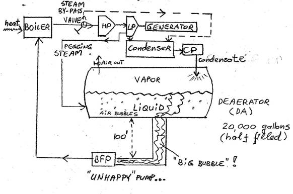
A power pump is a complex and complicated array of machinery, pipes, tanks, fuel, controls and all sorts of auxiliaries making a typical full PID diagram of a plant looking like a nightmare labyrinth. However, the essence of it can be visualized via a following diagram (Fig.1 ), and a video at www.pumpingmachinery.com/pump_school/pump_school.htm (click on PVA module #8, which is a visual accompaniment to this article).
Fuel (oil, gas, coal, sun, etc.) is supplied to heat the boiler to convert water (liquid) into steam. Temperature and pressure in a boiler are very high, feeding a high energy steam to a steam turbine, which typically has several stages (high, intermediate, low pressures). Many additional devices for better efficiency, control, reliability, etc. are present (superheater, desuperheater, numerous holding and overflow tanks, control valves, etc. etc.), but we will omit these for our purposes.
Fig. 1 Simplified diagram of a power plant cycle
Rotation of the steam turbine shaft is transmitted to a generator shaft, and electric current is delivered to a net. Exhausted steam is dumped to a condenser where it is further cooled to complete its transformation back to cold water, from where a condensate pump sends it to a deaerator (DA). The size of the DA varies depending on a design and plant power, but a 20,000 gallons tank, filled roughly half its capacity, can be assumed, for our purposes, as a typical size.
The purpose of a DA is mainly to remove entrained air (a boiler does not like the air), which is accomplished by an auxiliary (“pegging”) steam extracted from the LP steam turbine, which heats the water stripping it of most of the air, and keeping a DA at saturation temperature. The deaerated water flows to the inlet of a pump, which pumps it up to the boiler, and the cycles is repeated.
This works very well, until something unusual happens, such as a sudden reduction or complete of loss of generator load (load rejection condition). When generator trips, steam is quickly bypassed by the diverting valve around the steam turbine and typically directed into condenser. An alternative method is to dump it directly into a DA, or just went to the atmosphere, but these are less common. At roughly the same time, fuel is diverted from the boiler (gas is shut off, sun reflectors are deflected away, etc.), and a cool down of the boiler begins. Condensate pumps, however, continue to pump, in order to keep up with the (colder and colder) steam which continues to arrive to condenser. But the pegging steam is no longer available (the bypass valve diverted all steam to condenser), and it no longer pressurizes the DA, while at the same time the continuous arrival of the condensate cools the DA liquid – thus both temperature and pressure at the DA begin to drop: temperature due to cooling by the condensate, and pressure due to loss of (pressurizing) pegging steam.
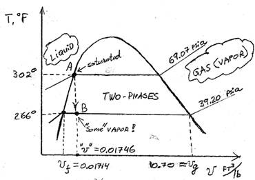
In order to understand what happens next, we need to take a brief refresher on basics of thermodynamics. Steam tables and graphs contain information relating pressure, temperature, specific volume, enthalpy (energy), entropy, and quality of water in various states: liquid, vapor (gaseous), and mixed. Various forms of diagrams exist (T-v, T-s, Mollier, etc.), but a T-v diagram is best for our purposes, as shown on Fig.2:
Fig. 2 T-v diagram, showing thermodynamics of the transient inside the Deaerator (DA transient)
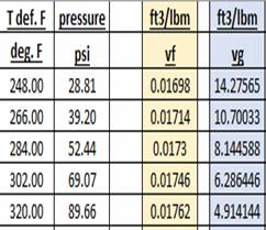
From the tables (such as, for example, ref. [1]), at 302 deg. F, 69.07 psia of pressure is required to keep water at saturation point “A”: if it was heated further at constant pressure (69.07 psia horizontal line leading to the right), it would eventually all boil out into vapor, which would occupy a huge volume (a lot more than the volume of the DA tank!). If, conversely, it was cooled (again, at constant pressure (69.07 psia in this case), it would become “subcooled”, with no vapor in it, but all purely liquid. Point “A” is thus a border line – saturation.
The DA is, however, a fixed volume tank, and thus should any vapor want to form there, the pressure would need to change. In our example, reduction in temperature (cooling by condensate due to loss of hot steam to DA) is a vertical movement downward on the diagram, from “A” to “B”, where we will stop at the assumed final temperature of 266 deg. F. The specific volume “v” is a ratio of the tank volume to a mass of fluid in the tank. A half full 20,000 gallons tank (1300 cubic feet) has 10,000 gallons of water in it, or 650 cubic feet. Liquid water weighs 57.27 lbs per each cubic foot at6 302 deg. F, and the inverse of that is 0.01746 ft3/lb, called specific volume. (The liquid in the tank thus weighs 650 x 57.27 = 37,225 lbs).
Point “B” is in mixed phase region. It shows 39.20 psia pressure per steam tables, with fluid in a two-phase state – some liquid and some vapor (gas). The specific volume at the temperature/pressure is 0.1714 ft3/lb for liquid (left intersection with saturation curve) and 10.70 ft3/lb for steam (right side intersection). The water quality “X” is a proportion of “gas” (vaporous water mass) to the total mass of mixture, x = Mg/M. With little math, it can be easily shown the formula for the average (total) specific volume is:
X = (v-vf) / (vg-vf)
In our case, “v” remains constant (tank is constant volume), = 1300 / 37225 = 0.035 ft3/lb, and so:
X = (0.035-0.01714) / (10.70033-0.01714) = 0.00167 = 0.17 % by mass.
This does not seem like a lot by mass, but is too much by volume. Mass of vapor is (only!) 0.17% x 37,225 lbs = 63 lbs which at 10.70 ft3/lb makes it a 63 x 10.70 = 674 ft3, which is nearly the same as volume of liquid! (which is only 650 ft3).
This massive and sudden creation of vapor cannot be contained in the tank (it is too small for it), and it gets sucked into the suction pipe (since the water is flowing to the pump), as a long nasty vapor bubble, or a cluster of them, stretching the entire length of the 100 feet suction header and making the suction pressure at the pump essentially the same as at the DA – i.e. a sudden loss of 100 feet of suction water head! Now, the pipe is mostly all vapor coming from the DA, - see also ref. [2].
Once vapor reaches pump suction, bad things happen. If a pump is equipped with suction pressure transmitter to trip, it will. If not, severe cavitation and vibrations will result – possibly wrecking the pump, or at least its mechanical seals, if it persists for some time. Many good pump designs, however, are capable to sustain such brief, albeit violent, transient, but even such – not for too long, perhaps 10-20 seconds.
Thus, if the overall plant control does not correct the issue shortly after the generator (load rejection or sudden reduction) trips, the problem will follow to the pump (and other things at the plant). That, however, is another discussion.
As noted, simplifications to the plant processes were made in this article, which may have additional effect on these types of transients, and possible remediation actions can be applied. One important aspects not addressed in this article is the fact the DA tank volume is initially only filled partially, and the void above it and what is happening there has a significant effect, but the specifics of the DA design and operation are not addressed here (you may however find it surprisingly important, and those of you with a sharp eye may let us know if the omission I made on that are significant and why).
Let us know the way YOU handle transients, - the best technique presented will get you a free admission to the next Pump School sessions (see schedule on our web link noted above).
Until then – keep transients at bay – and, - Keep-On-Pumping!
References 1. Cameron Hydraulic Data Book, 19th Edition, 2002 2. Rovnak, J., Wotring, T., Marshall, J., Evaluation of NPSH During Hot Restarts of Fossil Plants with Deaerators”, International Power Generating Conference, ASME, 91-JPGC-Pwr, 23, October 6-10, 1991
Dr. Lev Nelik, P.E. Editor, Pump Magazine On-Line December 2014
|